


Features
Standard
Specifications
Outline
Dimension
Drawings
Operation
Panel
Protective
Functions
OptionsInstructionsMotorCompatibilityWarrantyInquiry
Peripheral Devices
Why energy
savings?
Terminal Connection
Diagram
Terminal Specification
Explanation
Parameter
List
Explanations
of
Parameters
52
Line noise filter
FR-BSF01...for small
capacities
FR-BLF
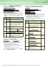
Outline dimension
Brake unit
BU-(H)
Electrical-discharge
resistor GZG type
GRZG type
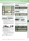
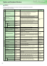
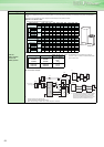
A brake unit is an option that fully enhances the regenerative braking capability of the inverter, and should be used with an electrical-discharge resistor.
Brake units should be selected according to the required braking torque.
(Note) 1. Connect so that the terminal symbols are the same for both inverter and brake unit. Incorrect connection will damage the inverter.
2. Minimize the cable length between the inverter and brake unit and between the discharging resistor and brake unit. Use a twisted cable when
the wiring length exceeds 2m.
(If twisted cables are used, the wiring length should be within 5m.)
Handling precautions
1. The thermal relay in the brake unit will trip if the rated torque is continuously output. After a trip, reset the inverter and increase its deceleration time
seting.
2. The maximum temperature rise of the discharging resistor is 100 °C. Use heat-resistant wires and wire to avoid contact with resistors.
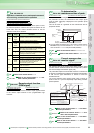
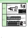
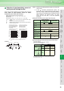
Name (type) Specifications, Structure, etc.
FR-BSF01 FR-BLF
(Note) 1. Each phase should be wound at least 3
times (4T, 4 turns) in the same direction.
(The greater the number of turns, the more
efficient.)
2. When the thickness of the wire prevents
winding, use at least 4 in series and ensure
that the current passes through each phase
in the same direction.
3. Can be used on the output side in the same
way as the input side.
4. Please use FR-BSF01 for inverters with
small capacities of 3.7K or less. Thick wires
(38mm
2
or more) can not be used. In such
cases, use the FR-BLF.
110
95
2-
φ
5
22.5
65
33
65
4.5
130
160
180
2.3 80
35
7
φ
7
31.5
Line noise filter
T/L3
S/L2
R/L1
Inverte
r
MCCB
Power
supply
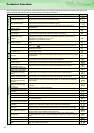
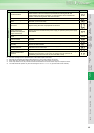
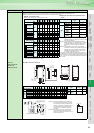
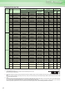
Brake unit selection table
* The inverter of 1.5K or less with 400V output can not be used in combination with a brake unit.
To use in combination with a brake unit, use the inverter of 2.2K or more.
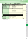
Combination of brake unit and electrical discharge resistor
Voltage
Motor(kW)
Braking
torque
0.75 1.5 2.2 3.7 5.5 7.5 11 15 18.5 22 30 37 45 55
200V
output
50%30s BU-1500 BU-3700 BU-7.5K BU-15K 2×BU-15K 3×BU-15K
4×
BU-15K
100%30s
BU-
1500
BU-
3700
BU-7.5K BU-15K 2×BU-15K 3×BU-15K
4×
BU-15K
5×
BU-15K
6×
BU-15K
7×
BU-15K
400V
output
50%30s * BU-H7.5K BU-H15K BU-H30K 2×BU-H30K
100%30s * BU-H7.5K BU-H15K BU-H30K 2×BU-H30K 3×BU-H30K
4×BU-
H30K
Voltage
Brake unit Resistor type Cable (P, N)
Voltage
Brake unit Resistor type Cable (P, N)
200V output
BU-1500 GZG300W-50Ω(one)
2mm
2
400V
output
BU-H7.5K
GRZG200-10Ω
(six in series)
2mm
2
BU-3700
GRZG200-10Ω
(three in series)
2mm
2
BU-H15K
GRZG300-5Ω
(eight in series)
3.5mm
2
BU-7.5K
GRZG300-5Ω
(four in series)
3.5mm
2
BU-H30K
GRZG400-2Ω
(twelve in series)
3.5mm
2
BU-15K
GRZG400-2Ω
(six in series)
3.5mm
2
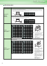
Brake unit
Discharge resistor
W
H
D
(Unit: mm)
Type W D H
BU-1500, 3700, 7.5K, 15K 100 128 240
BU-H7.5K, H15K, H30K 160 145 240
D
H
W
(Unit: mm)
Type W D H
GZG300W 335 40 78
GRZG200 306 26 55
GRZG300 334 40 79
GRZG400 411 40 79