Features
Standard
Specifications
Outline
Dimension
Drawings
Operation
Panel
Protective
Functions
OptionsInstructionsMotorCompatibilityWarrantyInquiry
Peripheral Devices
Why energy
savings?
Terminal Connection
Diagram
Terminal Specification
Explanation
Parameter
List
Explanations
of
Parameters
56
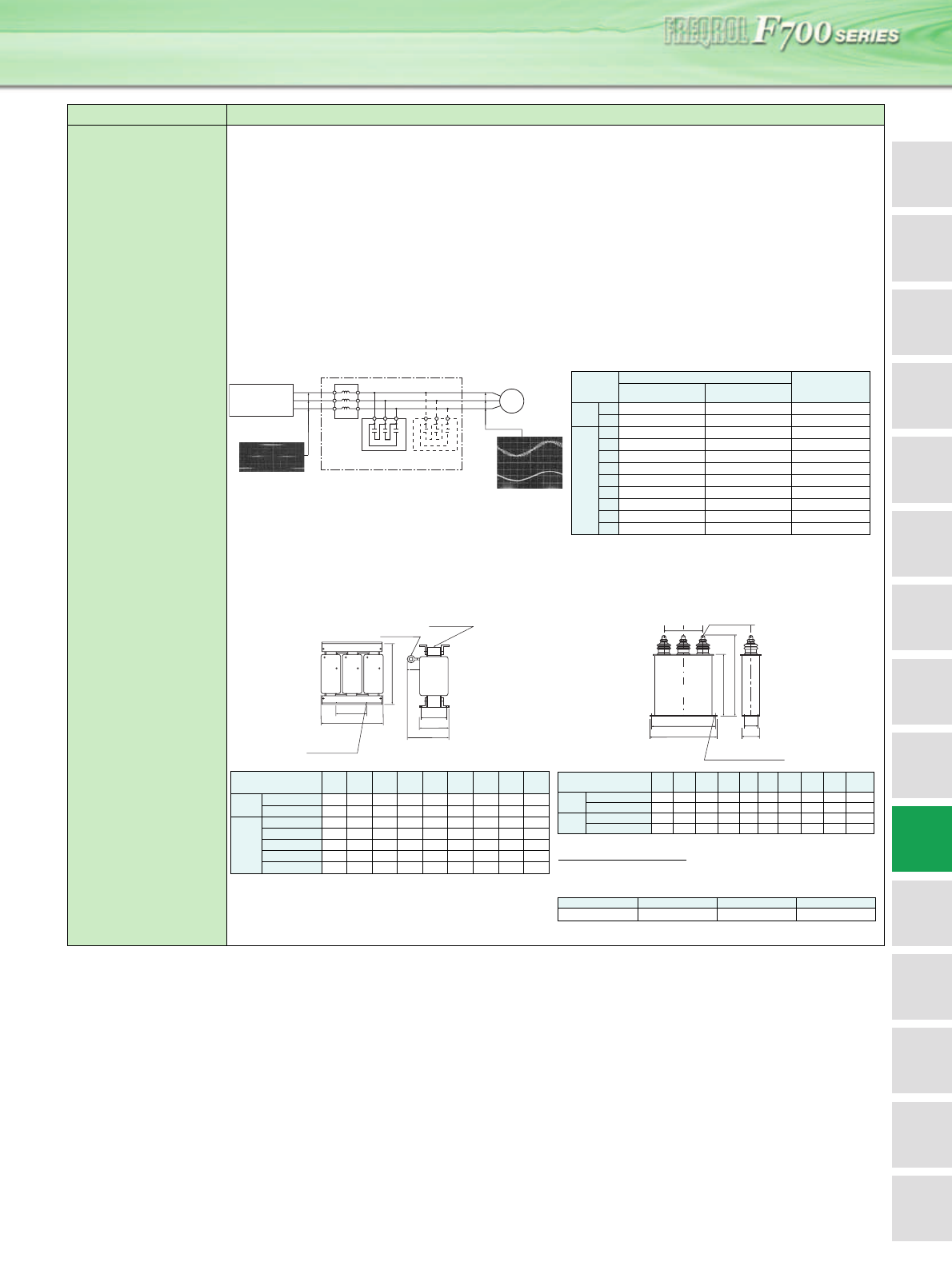
Sine wave filter
MT-BSL-(H)K
MT-BSC-(H)K
Application of the sine wave filter
For the FR-F700 series (75K or more) inverter, the motor voltage and current can be made to nearly sine wave shaped by providing a sine wave filter
on the output side.
1) Low noise
2) Surgeless
3) Motor loss reduction (use of standard motor)
Application condition
The following conditions have to be satisfied to install the sine wave filter.
1) Change the Pr. 72 setting to "25". (The initial value is "2".)
The carrier frequency changes to 2.5KHz. (The sine wave filter is designed on condition that the carrier frequency is 2.5KHz. Be sure to change
the setting properly.) If the inverter is operated with Pr.72 set to other than "25", the inverter and sine wave filter may be damaged.
2) The sine wave filter can be used only for 60 Hz or less inverter frequency.
Note that the filter can not be used for the higher frequency operation than this. (Otherwise the filter loss will increase. )
3) Use the inverter with capacity one rank higher. *2
4) Install an external thermal relay of the motor.
Circuit configuration and connection
Name (type) Specifications, Structure, etc.
Sine wave filter
FR-F700
Inverter
(Carrier 2.5kHz)
Inverter output
voltage
wave form
Capacitor (Capacitor)
Wave form at a
motor terminal
IM
Motor
U
V
W
X
Y
Z
voltage
current
+
-
0
Reactor
Install the filter near the inverter.
For a capacitor cable, use a cable
with size larger than indicated in the
table below "recommended cable
size ".
*
Motor
capacity
(kW)
Inverter type
Applied Inverter
(*2)
Reactor for filter Capacitor for filter
200V
class
75 MT-BSL-75K 1×MT-BSC-75K FR-F720-90K
90 MT-BSL-90K 1×MT-BSC-90K FR-F720-110K
400V
class
75 MT-BSL-H75K 1×MT-BSC-H75K FR-F740-90K
90 MT-BSL-H110K 1×MT-BSC-H110K FR-F740-110K
110 MT-BSL-H110K 1×MT-BSC-H110K FR-F740-132K
132 MT-BSL-H150K 2×MT-BSC-H75K FR-F740-160K
160 MT-BSL-H220K 2×MT-BSC-H110K FR-F740-185K
185 MT-BSL-H220K 2×MT-BSC-H110K FR-F740-220K
220 MT-BSL-H220K 2×MT-BSC-H110K FR-F740-250K
250 MT-BSL-H280K 3×MT-BSC-H110K FR-F740-280K
280 MT-BSL-H280K 3×MT-BSC-H110K FR-F740-315K
*1 For the 2 ×, connect capacitors in parallel as in the connection
diagram.
*2 If the rated motor current × (1.05 to 1.1) is less than 80% of the
inverter rated current, an inverter with same kW with a motor
can be used.
Reactor for sine wave filter Capacitor for sine wave filter
* Leave more than 25mm space between capacitors.
Recommended cable size
The cable sizes between the Inverter and MT-BSL and between the MT-
BSL and IM depend on U, V, W of "Peripheral devices list" (page 57)
The cable size to the MT-BSC is as table below.
Inverter type A B C D E F G H
Mass
(kg)
200V
class
MT-BSL-75K 330 150 285 185 216 328 M10 M12 80
MT-BSL-90K 390 150 320 180 220 330 M12 M12 105
400V
class
MT-BSL-H75K 330 150 285 185 216 318 M10 M10 80
MT-BSL-H110K 390 150 340 195 235 368 M12 M12 140
MT-BSL-H150K 455 200 397 200 240 380 M12 M12 190
MT-BSL-H220K 495 200 405 250 300 420 M12 M12 240
MT-BSL-H280K 575 200 470 310 370 485 M12 M12 340
C
B
A
4-G
installation
hole
W
Z
V
Y
U
X
Terminal H
Rating plate
D
E
F
Inverter type A B C D E F G H I
Mass
(kg)
200V
class
MT-BSC-75K 205 190 285 230 70 40 40 φ7M63.9
MT-BSC-90K 280 265 270 180 90 55 80 φ7 M12 5.5
400V
class
MT-BSC-H75K 205 190 220 170 70 40 50 φ7M63.0
MT-BSC-H110K 205 190 280 230 70 40 50 φ7M64.0
MT-BSC-75K MT-BSC-90K MT-BSC-H75K MT-BSC-H110K
38mm
2
38mm
2
22mm
2
22mm
2
B
A
Terminals I
GG
4-H
Installation hole
D
C
E
F


