


Features
Standard
Specifications
Outline
Dimension
Drawings
Operation
Panel
Protective
Functions
OptionsInstructionsMotorCompatibilityWarrantyInquiry
Peripheral Devices
Why energy
savings?
Terminal Connection
Diagram
Terminal Specification
Explanation
Parameter
List
Explanations
of
Parameters
34
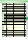
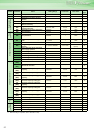
indicates simple mode parameters and indicates extended parameters. When setting parameters, refer to the instruction manual (applied) and understand instructions.
Pr.
Pr.
Without a fine parameter setting, the inverter automatically
performs energy saving operation.
This inverter is optimum for fan and pump applications.
If an alarm occurs, the inverter resets itself automatically to
restart. You can also select the alarm description for a retry.
When selection of automatic restart after instantaneous power
failure is selected (Pr. 57 Restart coasting time, restart operation is
performed at retry operation as at an instantaneous power
failure.)
Use Pr. 65 to select the alarm to be activated for retries.
"" indicates the alarms selected for retry.
Set the number of retries at alarm occurrence in Pr. 67.
Use Pr. 68 to set the waiting time from when an inverter alarm
occurs until a retry is made in the range 0 to 10s.
Reading the Pr. 69 value provides the cumulative number of
successful restart times made by retry.
Setting of the used motor selects the thermal characteristic
appropriate for the motor.
Setting is necessary when using a constant-torque motor.
Thermal characteristic of the electronic thermal relay function
suitable for the motor is set.
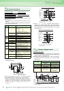
For the 5.5K and 7.5K, the Pr. 0 Torque boost and Pr. 12 DC injection
brake operation voltage settings are automatically changed
according to the Pr. 71 setting as follows.
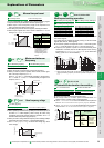
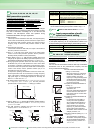
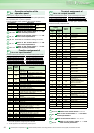
Energy saving control selection
Pr. 60 Setting Description
0 (initial value) Normal operation mode
4
Energy saving operation mode
In the energy saving operation mode, the inverter
automatically controls the output voltage to
minimize the inverter output voltage during a
constant operation.
9
Optimum excitation control mode
The optimum excitation control mode is a control
system which controls excitation current to
improve the motor efficiency to maximum and
determines output voltage as an energy saving
system.
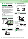
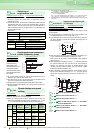
Retry function at alarm
occurrence
Pr.65 Retry selection
Pr.67 Number of retries at alarm occurrence
Pr.68 Retry waiting time Pr.69 Retry count display erase
Alarm Indication
for Retry
Pr.65 Setting
0 1 2 3 4 5
E.OC1
E.OC2
E.OC3
E.OV1
E.OV2
E.OV3
E.THM
E.THT
E.IPF
E.UVT
E.BE
E. GF
E.OHT
E.OLT
E.OPT
E.OP1
E. PE
E.PTC
E.CDO
E.SER
E.ILF
Pr.
60
Pr.60 Energy saving control
Pr.
65, 67 to 69
Pr. 67 Setting Description
0 (initial value) No retry function
1 to 10
Set the number of retries at alarm occurrence.
An alarm output is not provided during retry
operation.
101 to 110
Set the number of retries at alarm occurrence.
(The setting value of minus 100 is the number
of retries.)
An alarm output is provided during retry
operation.
66
Refer to the section about Pr. 22 and other
relevant parameters.
67 to 69
Refer to the section about Pr. 65 and
other relevant parameters.
70
Refer to the section about Pr. 30 and
other relevant parameters.
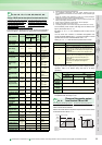
Use the constant torque motor
(applied motor)
Pr.71 Applied motor
Pr.71
Setting
Thermal Characteristic of the
Electronic Thermal Relay
Function
Motor
(: Motor used)
Standard
(SF-JR,
etc.)
Constant
torque
(SF-HRCA,
etc.)
0
(initial
value)
Thermal characteristics of a standard
motor
1
Thermal characteristics of the Mitsubishi
constant-torque motor
2
Thermal characteristics of a standard
motor
Adjustable 5 points V/F
20
Mitsubishi standard motor SF-JR4P
(1.5kW or less)
Pr.71
Standard Motor Setting
0, 2, 20
Constant Torque Motor
Setting
1
Pr. 0 3% 2%
Pr. 12 4% 2%
Pr.
Pr.
Pr.
Pr.
71