


37
indicates simple mode parameters and indicates extended parameters. When setting parameters, refer to the instruction manual (applied) and understand instructions.
Pr.
Pr.
Used to select the operation mode of the inverter.
You can freely change between operation by external signal
(external operation), operation by PU (FR-DU07) (PU operation),
operation by combination of PU operation and external operation
(external/PU combined operation) and network operation (when
RS-485 terminals or a communication option is used).
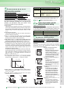
Specify operation mode at power on (Pr.340)
⋅
When power is switched on or when power comes back on after
instantaneous power failure, the inverter can be started up in the
network operation mode.
After the inverter has started up in the network operation mode,
parameter write and operation can be performed from a program.
Set this mode for communication operation using the inverter RS-
485 terminals or communication option.
⋅ You can set the operation mode at power on (reset) according
to the Pr. 79 and Pr. 340 settings.
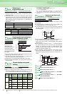
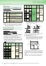
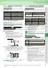
Providing optimum excitation to the motor can also produce high
torque in a low-speed region. (simple magnetic flux vector control)
⋅ Set the used motor capacity (equal to or one rank higher than the
inveter capacity) in Pr. 80.
⋅ The number of motor poles should be any of 2, 4 and 6 poles.
⋅ Single-motor operation (one motor for one inverter)
⋅ Wiring length from inverter to motor should be within 30m.
⋅ When simple magnetic flux vector control is not used, set "9999"
(initial value) in Pr. 80.
⋅ For Pr. 90 Motor constant (R1), normally setting is not necessary.
When you need more torque under simple magnetic flux vector
control for other manufacturer's motor, set the motor primary
resistance value (R1) for connection in Pr. 90
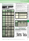
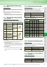
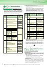
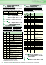
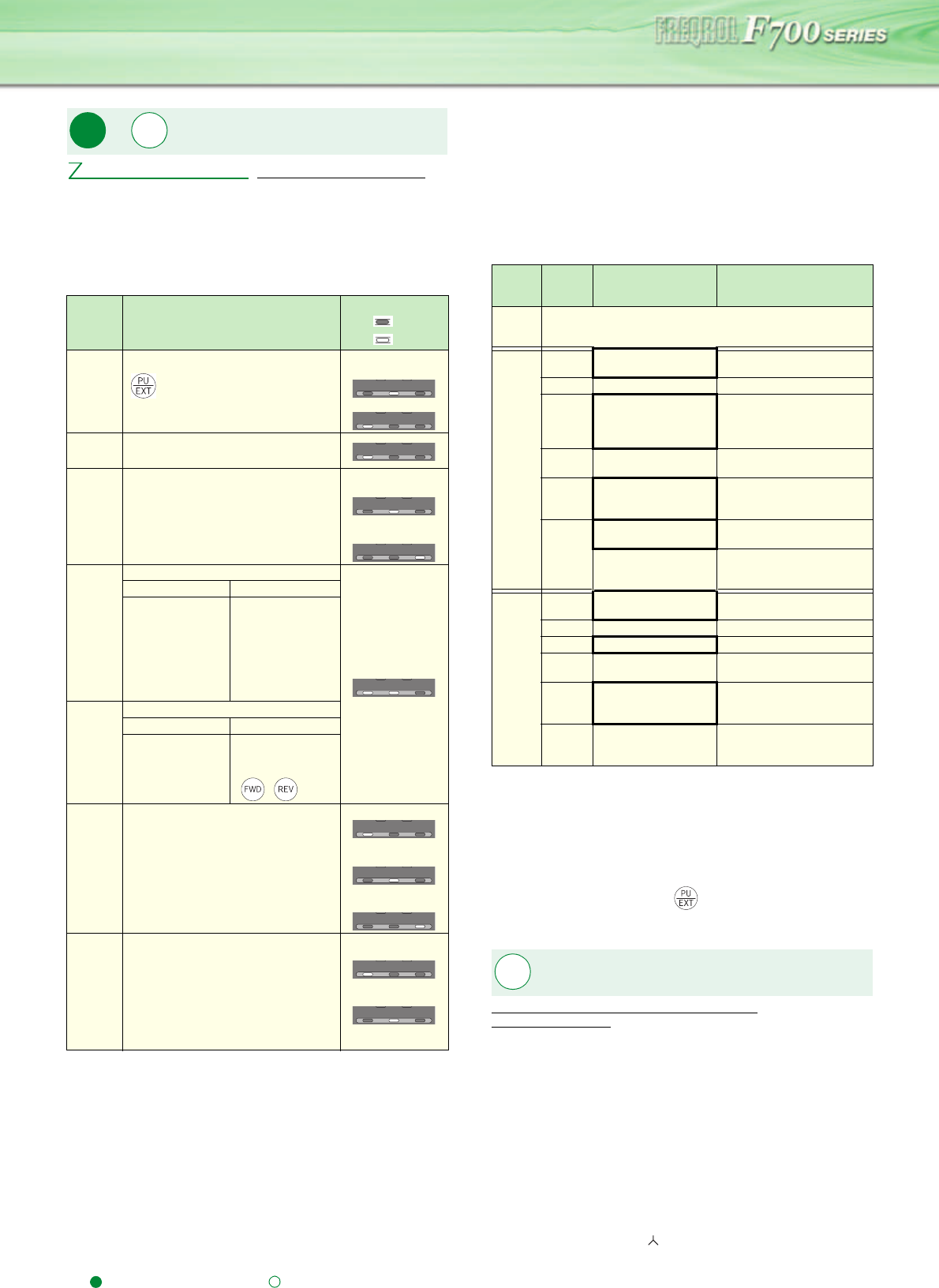
Operation mode selection
Pr.340 Communication startup mode selection
Pr.79
Setting
Description
LED Indication
:Off
:On
0
(initial
value)
External/PU switchover mode ( Press
to switch between the PU and
external operation mode.)
External operation mode at power-on
External operation
mode
PU operation mode
1 Fixed to PU operation mode
2
Fixed to external operation mode
Operation can be performed by switching
between the external and Net operation
mode.
External operation
mode
NET operation
mode
3
External/PU combined operation mode 1
Running frequency Start signal
PU (FR-DU07 /
FR-PU04) setting
or external signal
input (multi-speed
setting, across
terminals 4-5 (valid
when AU signal
turns on))
External signal
input (terminal STF,
STR)
4
External/PU combined operation mode 2
Running frequency Start signal
External signal
input (terminal 2, 4,
1, Jog, multi-speed
setting, etc)
Input from the PU
(FR-DU07 / FR-
PU04)
(, )
6
Switch-over mode
Switch among PU operation, external
operation, and NET operation while
keeping the same operation status.
PU operation mode
External operation
mode
NET operation
mode
7
External operation mode (PU operation
interlock)
X12 signal ON
Operation mode can be switched to the
PU operation mode.
(output stop during external operation)
X12 signal OFF
Operation mode can not be switched to
the PU operation mode.
PU operation mode
External operation
mode
Pr.
79
Pr.
340
Pr.79 Operation mode selection
PU EXT NET
PU EXT NET
PU EXT NET
PU EXT NET
PU EXT NET
PU EXT NET
PU EXT NET
PU EXT NET
PU EXT NET
PU EXT NET
PU EXT NET
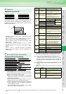
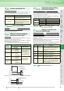
Pr. 340
Setting
Pr.79
Setting
Operation mode at
Power On, Power
Restoration, Reset
Operation Mode
Switchover
0
(initial
value)
As set in Pr. 79.
1, 2 *1
0 NET operation mode
Can be switched to external,
PU or NET operation mode
*2
1 PU operation mode Fixed to PU operation mode
2 NET operation mode
Can be switched to external
or NET operation mode
Switching to PU operation
mode disabled
3, 4
External/PU combined
operation mode
Operation mode switching
disabled
6 NET operation mode
Can be switched to external,
PU or NET operation mode
with operation continued
7
X12 (MRS) signal ON
..NET operation mode
Can be switched to external,
PU or NET operation mode
*2
X12(MRS)signal OFF
..External operation
mode
Fixed to external operation
mode (Forcibly switched to
external operation mode.)
10, 12
*1
0 NET operation mode
Can be switched to PU or
NET operation mode
*3
1 PU operation mode Fixed to PU operation mode
2 NEToperation mode Fixed to NET operation mode
3, 4
External/PU combined
operation mode
Operation mode switching is
disallowed
6 NET operation mode
Can be switched to PU or
NET operation mode with
operation continued
*3
7
External operation
mode
Fixed to external operation
mode (Forcibly switched to
external operation mode.)
*1 The Pr. 340 setting "2" or "12" is mainly used for communication
operation using the inverter RS-485 terminals.
When a value other than "9999" (selection of automatic restart after
instantaneous power failure) is set in Pr. 57 Restart coasting time, the
inverter will resume the same operation state which was in before after
power has been restored from an instantaneous power failure.
*2 The operation mode cannot be switched directly between the PU
operation mode and network operation mode.
*3 Operation mode can be changed between the PU operation mode and
network operation mode with key of the operation panel (FR-
DU07) and X65 signal.
Simple magnetic flux vector
control
Pr.80 Motor capacity (simple magnetic flux vector control)
Pr.90 Motor constant (R1)
Pr.
80, 90