


Features
Standard
Specifications
Outline
Dimension
Drawings
Operation
Panel
Protective
Functions
OptionsInstructionsMotorCompatibilityWarrantyInquiry
Peripheral Devices
Why energy
savings?
Terminal Connection
Diagram
Terminal Specification
Explanation
Parameter
List
Explanations
of
Parameters
44
indicates simple mode parameters and indicates extended parameters. When setting parameters, refer to the instruction manual (applied) and understand instructions.
Pr.
Pr.
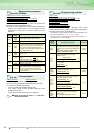
When the RS-485 terminals or communication option is used,
the external operation command and speed command can be
made valid. Also, the control command source in the PU
operation mode can be selected.
* Pr. 550 and Pr. 551 are always write-enabled.
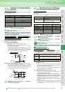
You can utilize the on/off of the inverter's output signals instead
of the remote output terminal of the programmable logic
controller.
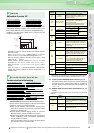
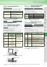
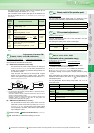
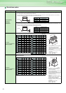
When the cumulative energization time of the inverter reaches
the parameter set time, the maintenance timer output signal
(Y95) is output. (MT) is displayed on the operation panel
(FR-DU07)
This can be used as a guideline for the maintenance time of
peripheral devices.
The cumulative energization time of the inverter is stored into the
EEPROM every hour and indicated in Pr. 503 Maintenance timer in
100h increments. Pr. 503 is clamped at 9998 (999800h).
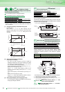
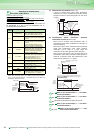
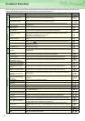
The average value of the output current during constant speed
operation and the maintenance timer value are output as a pulse to
the current average value monitor signal (Y93).
The pulse width output to the I/O module of the PLC or the like can
be used as a guideline due to abrasion of machines and elongation
of belt and for aged deterioration of devices to know the
maintenance time.
The current average value monitor signal (Y93) is output as
pulse for 20s as 1 cycle and repeatedly output during constant
speed operation.
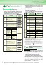
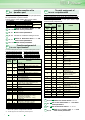
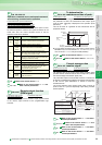
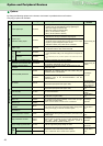
Operation command source and speed command
source during communication operation
Pr.338 Communication operation command source
Pr.339 Communication speed command source
Pr.550 NET mode operation command source selection
Pr.551 PU mode operation command source selection
Pr.
Number
Setting
Range
Description
338
0
(initial
value)
Operation command source communication
1 Operation command source external
339
0
(initial
value)
Speed command source communication
1
Speed command source external (Frequency
setting from communication is invalid, terminal 2
and 1 setting from external is valid)
2
Speed command source external (Frequency
setting from communication is valid, terminal 2 and
1 setting from external is invalid)
550
*
0 Communication option valid
1 Inverter RS-485 terminal valid
9999
(initial
value)
Automatic communication option recognition
Normally, the RS-485 terminals are valid. When
the communication option is fitted, the
communication option is valid.
551
*
1
Select the RS-485 terminals as the PU operation
mode control source.
2
(initial
value)
Select the PU connector as the PU operation
mode control source.
340
Refer to the section about Pr. 79.
341 to 343
Refer to the section about Pr. 117 and
other relevant parameters.
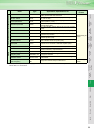
Remote output function
(REM signal)
Pr.495 Remote output selection Pr.496 Remote output data 1
Pr.497 Remote output data 2
Pr.
338, 339, 550, 551
Pr.
Pr.
Pr.
495 to 49
7
To determine the
maintenance time of parts.
Pr.503 Maintenance timer
Pr.504 Maintenance timer alarm output set time
549
Refer to the section about Pr.117 to Pr. 124.
550 to 551
Refer to the section about
Pr. 338, Pr.339
.
Current average value
monitor signal
Pr.555 Current average time Pr.556 Data output mask time
Pr.557 Current average value monitor signal output reference current
571
Refer to the section about Pr. 13 and other
relevant parameters.
575 to 577
Refer to the section about Pr. 127 and
other relevant parameters.
611
Refer to the section about Pr. 57 and other
relevant parameters.
872
Refer to the section about Pr. 251 and other
relevant parameters.
Pr.
503 to 50
4
First power ON
Maintenance
timer
(Pr. 503)
Set "0" in Pr.503
Y95 signal
MT display
OFF ON
Time
ON
Pr.504
9998
(999800h)
Pr.
Pr.
Pr.
555 to 55
7
Y93 signal
1) Data output mask time
2) Start pulse
1 cycle (20s)
3) Output current average value pulse
Next cycle
Time
Output
frequency
From acceleration to constant speed operation
Signal output time=
output current average value (A)
Pr.557 (A)
5s
4) Maintenance timer pulse
Signal output time=
5s
40000h
5) End pulse
The averaged current value is output as low pulse shape for
0.5 to 9s (10 to 180%) during start bit output.
When the speed has changed to constant
from acceleration/deceleration, Y93 signal is
not output for Pr.556 time.
Pr.503 1000h
output as low pulse
shape for 1 to 16.5s
The maintenance timer value (Pr.503) is output
as Hi output pulse shape for 2 to 9s (16000h to
72000h).
Output as Hi pulse shape for 1s (fixed)
Time and output current set in Pr.555 are averaged
Pr.
Pr.
Pr.
Pr.