


Features
Standard
Specifications
Outline
Dimension
Drawings
Operation
Panel
Protective
Functions
OptionsInstructionsMotorCompatibilityWarrantyInquiry
Peripheral Devices
Why energy
savings?
Terminal Connection
Diagram
Terminal Specification
Explanation
Parameter
List
Explanations
of
Parameters
54
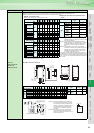
Brake unit
MT-BU5-(H)K
Resistor unit
MT-BR5-(H)K
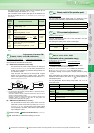
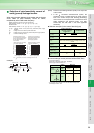
The brake unit and resistor unit are options that will fully exhibit the regenerative braking capability of the inverter. Use them as a set.
There are six different brake units as in the following table, from which make selection according to the deceleration time.
When the brake unit duty (%ED) excess and an alarm occur, errors appear in the inverter.
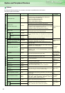
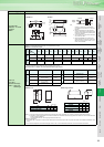
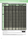
Outline dimension drawings
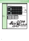
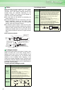
External connection diagram
Name (type) Specifications, Structure, etc.
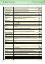
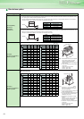
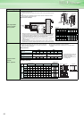
Brake unit selection table
%ED at short-time rating when braking torque is 100%
Motor Capacity
75
kW
90
kW
110
kW
132
kW
160
kW
185
kW
220
kW
280
kW
375
kW
Inverter
200V 75K 90K
110K
------ ------ ------ ------ ------ ------
400V 75K 90K
110K
132K 160K 185K 220K 280K 375K
Brake unit
2
0
0
V
MT-BU5-55K
%ED
5 ------ ------ ------ ------ ------ ------ ------ ------
MT -B U5-1 10 K 20 1 5 1 0 ------ ------ ------ ------ ------ ------
4
0
0
V
MT-BU5-H75K
%ED
1 0 5 ------ ------ ------ ------ ------ ------ ------
MT-BU5-H150K 40 25 20 10 5 5 ------ ------ ------
MT-BU5-H220K 80 60 40 25 15 10 10 5 ------
MT-BU5-H280K ------ 80 65 40 30 20 15 10 5
MT-BU5-H375K ------ ------ ------ 80 50 40 20 15 10
Braking torque (%) at short-time rating
Motor Capacity
75
kW
90
kW
110
kW
132
kW
160
kW
185
kW
220
kW
280
kW
375
kW
Inverter
200V 75K 90K
110K
------ ------ ------ ------ ------ ------
400V 75K 90K
110K
132K 160K 185K 220K 280K 375K
Brake unit
2
0
0
V
MT-BU5-55K
braking
torque
(%)
70 60 50 ------ ------ ------ ------ ------ ------
MT-BU5-110K 150 120 100 ------ ------ ------ ------ ------ ------
4
0
0
V
MT-BU5-H75K
braking
torque
(%)
100 80 70 55 45 40 35 25 20
MT-BU5-H150K 150 150 135 110 90 80 70 50 40
MT-BU5-H220K 150 150 150 150 135 115 100 80 55
MT-BU5-H280K 150 150 150 150 150 150 125 100 70
MT-BU5-H375K 150 150 150 150 150 150 150 130 100
* To obtain a large braking torque, the motor has to have a torque characteristic
that meets the braking torque.
Check the torque characteristic of the motor.
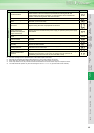
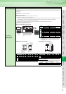
Brake unit and resistor unit combinations and
cables
(Caution 1) Be sure to select the well-ventilated place for installa-
tion of the resistor unit. Ventilation is necessary when
installing the resistor in a place, e.g. enclosure, where
heat is not well diffused.
(Caution 2) The temperature rise of the discharging resistor is
300deg. Therefore, wire the cable so as not to touch
the resistor. In addition, separate the parts with low
heat resistance and the resistor by at least 40 to
50cm.
(Caution 3) The temperature of the resistor unit abnormally
increases if the brake unit is operated exceeding the
specified duty. Since the resistor unit may result in
overheat if the temperature of the brake unit is left
unchanged, switch off the inverter.
* The resistor unit is provided with a thermostat (a contact) as
overheat protection. If this protective device is activated under
normal operation, it is assumed that the deceleration time is too
short. In such a case, increase the deceleration time setting of
the inverter.
Brake Unit Type
Resistor unit
type
Cable
200V
MT-BU5-55K MT-BR5-55K
14mm
2
MT-BU5-110K 2×MT-BR5-55K
2×14mm
2
400V
MT-BU5-H75K MT-BR5-H75K
14mm
2
MT-BU5-
H150K
2×MT-BR5-H75K
2×14mm
2
MT-BU5-
H220K
3×MT-BR5-H75K
3×14mm
2
MT-BU5-
H280K
4×MT-BR5-H75K
4×14mm
2
MT-BU5-
H375K
5×MT-BR5-H75K
5×14mm
2
BBA
AA
AB
A
30075 75
4507.5
L
C
LP
LN
CN8
P
N
X-Y
C
P, PR terminal
M6
P PRTH1
TH2
E
M4
193 189
480
510
85
85800
37 60 2110
40
30
NP
4 7
Mounting hole
2 M6 screw N
4 15
Mounting hole
Brake Unit Type
A AA AB B BA C Lc LP LN N
Approx.
mass
X Y Z
200V
class
MT-BU5-55K 118 102 90 200 100 256.5 550 1740 1740 1 1.5 14 12 8
MT-BU5-110K 188 172 160 200 100 256.5 550 2000 2000 2 3.0 22 12 8
400V
class
MT-BU5-H75K 118 102 90 200 100 256.5 550 1740 1740 1 1.5 14 12 8
MT-BU5-H150K 188 172 160 200 100 256.5 550 2000 2000 2 3.0 22 12 8
MT-BU5-H220K 258 242 230 200 100 256.5 550 2000 2000 3 4.5 38 12 8
MT-BU5-H280K 328 312 300 200 100 256.5 550 2330 2330 4 6.0 60 12 10
MT-BU5-H375K 398 382 370 200 100 256.5 550 2330 2330 5 7.5 60 12 10
Resistor unit
type
Resistance
value
mass
200V
class
MT-BR5-55K 2.0Ω 50kg
400V
class
MT-BR5-
H75K
6.5Ω 70kg
(Caution 1) For wiring of the brake unit and inverter, use
an accessory cable supplied with the brake
unit. Connect the main circuit cable to the ter-
minals P/+ and N/- and connect the control cir-
cuit cable to the connector (CN8) inside by
making cuts in the rubber bush at the top of
the inverter.
(Caution 2) The brake unit which uses multiple resistor
units has terminals equal to the number of
resistor units. Connect one resistor unit to one
pair of terminals (P, PR).
R/L1
T/L3
S/L2
U
W
V
N/-
P/+
IM
CN8
TH1 TH2
PR
P
PR
P
P
PR
P
PR
Inverter
Cable provided with a brake unit
Brake unit
MT-BU5
Resistor unit
MT-BR5
The wiring length should be 10m
maximum when wires are twisted
and 5m maximum when wires are
not twisted.
Inverter
Brake unit