


Features
Standard
Specifications
Outline
Dimension
Drawings
Operation
Panel
Protective
Functions
OptionsInstructionsMotorCompatibilityWarrantyInquiry
Peripheral Devices
Why energy
savings?
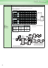
Terminal Connection
Diagram
Terminal Specification
Explanation
Parameter
List
Explanations
of
Parameters
48
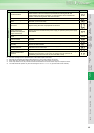
*1 Resetting the inverter initializes the internal thermal integrated data of the electronic thermal relay function.
*2 The error message shows an operational error. The inverter output is not shut off.
*3 Warnings are messages given before major failures occur. The inverter output is not shut off.
*4 Minor faults warn the operator of failures with output signals. The inverter output is not shut off.
*5 When major failures occur, the protective functions are activated to shut off the inverter output and output the alarms.
*6 The external thermal operates only when the OH signal is set in Pr. 178 to Pr. 189 (input terminal function selection).
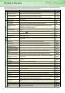
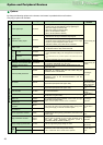
Major failures
*5
PU disconnection
Appears when a communication error between the PU and inverter occurred, the
communication interval exceeded the permissible time during the RS-485
communication with the PU connecter, or communication errors exceeded the
number of retries during the RS-485 communication.
Retry count excess Appears when the operation was not restarted within the set number of retries.
Parameter storage devide
alarm
Appears when operation of the element where parameters stored became
abnormal. (main circuit board)
CPU error Appears during the CPU and peripheral circuit errors.
/
/
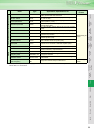
Operation panel power
supply short circuit
RS-485 terminals power
supply short circuit
Appears when the RS-485 terminal power supply or operation panel power supply
was shorted.
24VDC power output short
circuit
Appears when terminals PC-SD were shorted.
Output current detection
value exceeded
Appears when output current exceeded the output current detection level set by the
parameter.
Inrush resistor overheat Appears when the resistor of the inrush current limit circuit overheated.
Communication error
(inverter)
Appears when a communication error occurred during the RS-485 communication
with the RS-485 terminals.
Analog input error
Appears when 30mA or more is input or a voltage (7.5V or more) is input with the
terminal 2/4 set to current input.
Internal circuit error Appears when an internal circuit error occurred.
Brake transistor alarm
detection
This function stops the inverter output if an alarm occurs in the brake circuit, e.g.
damaged brake transistors. In this case, the inverter must be powered off
immediately. (Internal circuit error for the model 55K or less)
Function Name Description Indication