


Features
Standard
Specifications
Outline
Dimension
Drawings
Operation
Panel
Protective
Functions
OptionsInstructionsMotorCompatibilityWarrantyInquiry
Peripheral Devices
Why energy
savings?
Terminal Connection
Diagram
Terminal Specification
Explanation
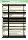
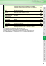
Parameter
List
Explanations
of
Parameters
42
indicates simple mode parameters and indicates extended parameters. When setting parameters, refer to the instruction manual (applied) and understand instructions.
Pr.
Pr.
You can control the operation of the cooling fan (200V class
2.2K or more, 400V class 3.7K or more) built in the inverter.
The inverter output current may be used to assume motor slip to
keep the motor speed constant.
Used to select the stopping method (deceleration to a stop or
coasting) when the start signal turns off.
Used to stop the motor with a mechanical brake, etc. together
with switching off of the start signal.
You can also select the operations of the start signals (STF/STR).
When Pr. 250 is set to "9999" (initial value) or "8888".
When Pr. 250 is set to values other than "9999" (initial value) or "8888".
You can disable the output phase failure protection function that
stops the inverter output if one of the inverter output side (load
side) three phases (U, V, W) opens.
The input phase failure protection selection of the inverter input
side (R/L1, S/L2, T/L3) can be made valid.
Degrees of deterioration of main circuit capacitor, control circuit
capacitor or inrush current limit circuit and cooling fan can be
diagnosed by monitor.
When any part has approached the end of its life, an alarm can
be output by self diagnosis to prevent a fault.
(Use the life check of this function as a guideline since the life
except the main circuit capacitor is calculated theoretically.)
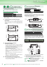
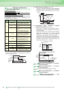
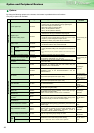
Increase cooling fan life
Pr.244 Cooling fan operation selection
Pr. 244 Setting Description
0
The cooling fan operates at power on.
Cooling fan on/off control invalid (The cooling
fan is always on at power on)
1 (initial value)
Cooling fan on/off control valid
The fan is normally on during inverter
operation. The fan switches on/off according to
the temperature during a stop of the inverter
whose status is monitored.
Slip compensation
Pr.245 Rated slip Pr.246 Slip compensation time constant
Pr.247 Constant-output region slip compensation selection
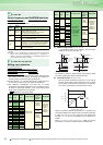
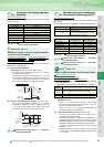
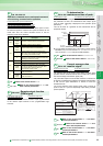
Selection of motor stopping
method and start signal
Pr.250 Stop selection
Pr.250
Setting
Description
Start signal
(STF/STR)
Stop operation
0 to 100s
STF signal: Foward
rotation start
STR signal: Reverse
rotation start
The motor is coasted to a
stop when the preset time
elapses after the start
signal is turned off. The
motor is coasted to a stop
(Pr. 250 - 1000)s after the
start signal is turned off.
1000s to 1100s
STF signal: Start signal
STR signal: Forward/
reverse
rotation signal
9999
STF signal: Foward
rotation start
STR signal: Reverse
rotation start
When the start signal is
turned off, the motor
decelerates to stop.
8888
STF signal: Start signal
STR signal: Forward/
reverse
rotation signal
Pr.
244
Pr.
245 to 24
7
Pr.
250
Time
ON
OFF
Start
signal
Deceleration starts
when start signal turns off
Deceleration time
(Time set in Pr. 8, etc.)
DC brake
Output frequency
(Hz)
ON
OFF
RUN
signal
OFF
ON
Start signal
Output is shut off when set
time elapses after start signal
turned off
Pr.250
Motor coasts to stop
Time
O
FF
RUN signal
Output frequency
(Hz)
ON
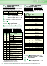
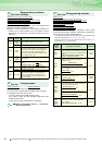
Input/output phase failure
protection selection
Pr.251 Output phase failure protection selection
Pr.872 Input phase failure protection selection
Pr. Number Setting Range Description
251
0 Without output phase failure protection
1 (initial value) With output phase failure protection
872
0 (initial value) Without input phase failure protection
1 With input phase failure protection
252, 253
Refer to the section about Pr. 73 and
other relevant parameters.
Display of the life of the
inverter parts
Pr.255 Life alarm status display Pr.256
Inrush current limit circuit life display
Pr.257
Control circuit capacitor life display
Pr.258
Main circuit capacitor life display
Pr.259 Main circuit capacitor life measuring
Pr.
Number
Setting
Range
Description
255 (0 to 15)
Display whether the control circuit capacitor,
main circuit capacitor, cooling fan, and each
parts of the inrush current limit circuit has
reached the life alarm output level or not.
Reading only
256 (0 to 100%)
Display the deterioration degree of the inrush
current limit circuit. Reading only
257 (0 to 100%)
Display the deterioration degree of the control
circuit capacitor. Reading only
258 (0 to 100%)
Display the deterioration degree of the main
circuit capacitor. Reading only
The value measured by Pr. 259 is displayed.
259
0, 1
(2, 3, 8, 9)
Setting "1" and turning off the power starts the
measurement of the main circuit capacitor life.
When the Pr. 259 value is "3" after powering on
again, the measuring is completed. Read the
deterioration degree in Pr. 258.
260
Refer to the section about Pr. 72.
Pr.
251, 872
Pr.
Pr.
255 to 259
Pr.