


51
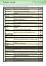
Stand-alone option
Name (type) Specifications, Structure, etc.
Intercompatibility
attachment
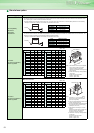
FR-AAT
FR-A5AT
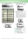
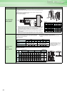
FR-F500 series intercompatibility attachment
The FR-F700 series inverter can be installed using installation holes of the conventional FR-F500 series with this attachment.This attachment is use-
ful for replacing the conventional model with the FR-F700 series.
Since the installation size of the 400V class 0.75K to 3.7K, 7.5K, 22K, 37K to 55K are the same, an intercompatibility attachment is not necessary
* The depth increases after installation of the inverter when the attachment is used.
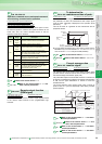
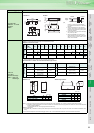
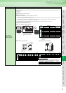
FR-A100E and FR-A200E series installation intercompatibility attachment
The FR-F700 series inverter can be installed using installation holes of the conventional FR-A100E and FR-A200E series with this attachment. This
attachment is useful for replacing the conventional model with the FR-F700 series.
* The depth increases after installation of the inverter when the attachment is used
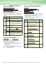
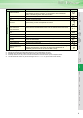
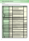
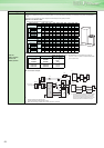
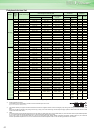
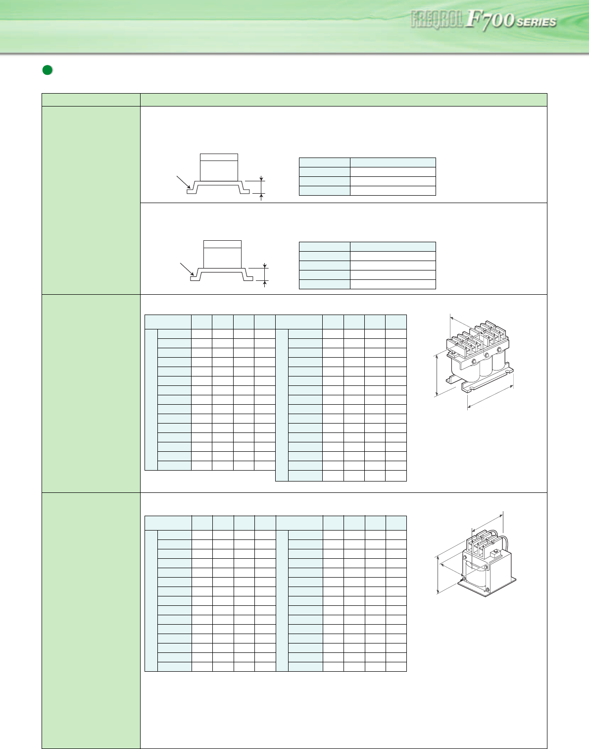
AC reactor
(for power coordination)
FR-HAL-(H)K
Outline dimension
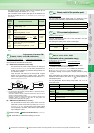
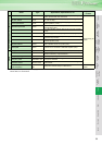
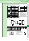
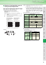
DC reactor
(for power coordination)
FR-HEL-(H)K
Outline dimension
Inverter
FR-AAT
12
Type Applied Inverter
FR-AAT22
FR-F740-5.5K
FR-AAT24
FR-F740-15K, 18.5K
FR-AAT27
FR-F740-30K
Inverter
FR-A5AT
12
Type Applied Inverter
FR-A5AT02
FR-F740-0.75K to 3.7K
FR-A5AT03
FR-F740-5.5K to 11K
FR-A5AT04
FR-F740-15K to 22K
FR-A5AT05
FR-F740-45K, 55K
(Unit: mm)
Type W D H
Mass
(kg)
Type W D H
Mass
(kg)
2
0
0
V
0.4K
104 72 99 0.6
4
0
0
V
H0.4K
135 59.6 115 1.5
0.75K
104 74 99 0.8
H0.75K
135 59.6 115 1.5
1.5K
104 77 99 1.1
H1.5K
135 59.6 115 1.5
2.2K
115 77 115 1.5
H2.2K
135 59.6 115 1.5
3.7K
115 83 115 2.2
H3.7K
135 70.6 115 2.5
5.5K
115 83 115 2.3
H5.5K
160721423.5
7.5K
130 100 135 4.2
H7.5K
160911425.0
11K
160 111 164 5.2
H11K
160911466.0
15K
160 126 167 7.0
H15K
220 105 195 9.0
18.5K
160 175 128 7.1
H18.5K
220 170 215 9.0
22K
185 158 150 9.0
H22K
220 170 215 9.5
30K
185 168 150 9.7
H30K
220 170 215 11
37K
210 174 175 12.9
H37K
220 170 214 12.5
45K
210 191 175 16.4
H45K
280 165 245 15
55K
210 201 175 17.4
H55K
280 170 245 18
H75K
205 208 170 20
(Note) 1. Make selection according to the applied
motor capacity. (When the inverter
capacity is larger than the motor
capacity, make selection according to the
motor capacity)
2. Power factor improving reactor (FR-BAL)
can be used.
Power factor improving effect
FR-BAL : approx. 90%
FR-HAL : approx. 88%
H
W
Less than D
(Unit: mm)
Type W D H
Mass
(kg)
Type W D H
Mass
(kg)
2
0
0
V
0.4K
70 61 71 0.4
4
0
0
V
H0.4K
90 60 78 0.6
0.75K
85 61 81 0.5
H0.75K
66 70 100 0.8
1.5K
85 70 81 0.8
H1.5K
66 80 100 1
2.2K
85 70 81 0.9
H2.2K
76 80 110 1.3
3.7K
77 82 92 1.5
H3.7K
86 95 120 2.3
5.5K
77 92 92 1.9
H5.5K
96 100 128 3
7.5K
86 98 113 2.5
H7.5K
96 105 128 3.5
11K
105 112 133 3.3
H11K
105 110 137 4.5
15K
105 115 133 4.1
H15K
105 125 152 5
18.5K
105 165 93 4.7
H18.5K
114 120 162 5
22K
105 175 93 5.6
H22K
133 120 178 6
30K
114 200 100 7.8
H30K
133 120 178 6.5
37K
133 195 117 10
H37K
133 155 187 8.5
45K
133 205 117 11
H45K
133 170 187 10
55K
153 209 132 12.6
H55K
152 170 206 11.5
(Note) 1.Be sure to remove the jumper across
terminals P/+ - P1 of the inverter. (A
failure to do so will produce no power
factor improving effect)
2. The wiring length between the reactor and
inverter should be within 5m.
3. The size of the cables used should be equal
to or larger than that of the power supply
cables (R/L1, S/L2, T/L3).
4. Make selection according to the motor
capacity.
(When the inverter capacity is larger than
the motor capacity, make selection
according to the motor capacity)
5. Power factor improving reactor (FR-BEL)
can be used.
Power factor improving effect
FR-BEL : approx. 95%
FR-HEL : approx. 93%
H
W
Less than D