


17
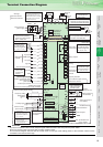
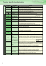
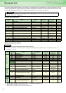
Type Terminal Symbol Terminal Name Description
Main circuit
R/L1, S/L2, T/L3 AC power input Connect to the commercial power supply.
U, V, W Inverter output Connect a three-phase squirrel-cage motor.
R1/L11, S1/L21
Power supply for control
circuit
Connected to the AC power supply terminals R/L1 and S/L2. To retain the alarm display and
alarm output, apply external power to this terminal.
P/+, N/- Brake unit connection
Connect the brake unit (FR-BU, BU, MT-BU5), power regeneration common converter (FR-
CV), power regeneration converter (MT-RC) or high power factor converter (FR-HC, MT-HC).
P/+, P1 DC reactor connection
For the 55K or less, remove the jumper across terminals P/+ - P1 and connect the DC reactor.
(For the 75K or more, a DC reactor is supplied as standard.)
PR, PX Please do not remove or use terminals PR and PX or the jumper connected.
Earth (Ground) For earthing (grounding) the inverter chassis. Must be earthed (grounded).
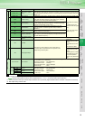
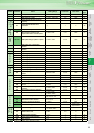
Control circuit input signal
Contact input
STF Forward rotation start
Turn on the STF signal to start forward rotation and turn it off to
stop.
When the STF and STR
signals are turned on
simultaneously, the stop
command is given.
STR Reverse rotation start
Turn on the STR signal to start reverse rotation and turn it off to
stop.
STOP
Start self-holding
selection
Turn on the STOP signal to self-hold the start signal.
RH, RM, RL Multi-speed selection Multi-speed can be selected according to the combination of RH, RM and RL signals.
JOG Jog mode selection
Turn on the JOG signal to select Jog operation (initial setting) and turn on the start signal (STF
or STR) to start Jog operation.
RT
Second acceleration/
deceleration time
selection
Turn on the RT signal to select second acceleration/deceleration time.
When the second function such as "second torque boost" and "second V/F (base frequency)"
are set, turning on the RT signal selects these functions.
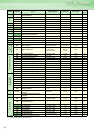
MRS Output stop
Turn on the MRS signal (20ms or more) to stop the inverter output.
Use to shut off the inverter output when stopping the motor by electromagnetic brake.
RES Reset
Used to reset alarm output provided when protective function is activated. Turn on the RES
signal for more than 0.1s, then turn it off.
Recover about 1s after reset is cancelled.
AU
Terminal 4 input selection
Terminal 4 is made valid only when the AU signal is turned on. (The frequency setting signal
can be set between 4 and 20mADC.)
Turning the AU signal on makes terminal 2 (voltage input) invalid.
PTC input
AU terminal is used as PTC input terminal (thermal protection of the motor). When using it as
PTC input terminal, set the AU/PTC switch to PTC.
CS
Selection of automatic
restart after
instantaneous power
failure
When the CS signal is left on, the inverter restarts automatically at power restoration. Note that
restart setting is necessary for this operation. In the initial setting, a restart is disabled.
SD
Contact input common
(sink)
Common terminal for contact input terminal (sink logic) and terminal FM. Common output
terminal for 24VDC 0.1A power supply (PC terminal). Isolated from terminals 5 and SE.
PC
External transistor
common,
24VDC power supply,
contact input common
(source)
When connecting the transistor output (open collector output), such as a programmable
controller (PLC), when sink logic is selected, connect the external power supply common for
transistor output to this terminal to prevent a malfunction caused by undesirable currents. Can
be used as 24VDC 0.1A power supply. When source logic has been selected, this terminal
serves as a contact input common.
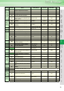
Frequency setting
10E
Frequency setting power
supply
When connecting the frequency setting potentiometer at an initial
status, connect it to terminal 10.
Change the input specifications when connecting it to terminal 10E.
10VDC, permissible load
current 10mA.
10
5VDC, Permissible load
current 10mA.
2
Frequency setting
(voltage)
Inputting 0 to 5VDC (or 0 to 10V, 4 to 20mA) provides the maximum output frequency at 5V
(10V, 20mA) and makes input and output proportional. Use Pr.73 to switch from among input 0
to 5VDC (initial setting), 0 to 10VDC, and 4 to 20mA.
Voltage input: Input resistance 10kΩ ± 1kΩ Maximum permissible voltage 20VDC
Current input: Input resistance 250Ω ± 2% Maximum permissible current 30mA
4
Frequency setting
(current)
Inputting 4 to 20mADC (or 0 to 5V, 0 to 10V) provides the maximum output frequency at 20mA
(5V, 10V) makes input and output proportional. This input signal is valid only when the AU
signal is on (terminal 2 input is invalid). Use Pr.267 to switch between the input 4 to 20mA and 0
to 5VDC, 0 to 10VDC (initial setting).
Voltage input: Input resistance 10kΩ ± 1kΩ Maximum permissible voltage 20VDC
Current input: Input resistance 250Ω ± 2% Maximum permissible current 30mA
1
Frequency setting
auxiliary
Inputting 0 to ±5 VDC or 0 to ±10VDC adds this signal to terminal 2 or 4 frequency setting
signal. Use Pr.73 to switch between the input 0 to ±5VDC and 0 to ±10VDC (initial setting).
Input resistance 10kΩ ± 1kΩ, Maximum permissible voltage ± 20VDC
5
Frequency setting
common
Common terminal for frequency setting signal (terminal 2, 1 or 4) and analog output terminal
AM. Do not earth (ground).
Terminal Specification Explanation