Reference Manual
00809-0100-2230, Rev BB
August 2014
Rosemount 2230
3-6
Section 3. Installation
3.3 ELECTRICAL
INSTALLATION
3.3.1 Cable/Conduit
Entries
The electronics housing has three entries, two M20×1.5 and one M25×1.5
(Optional: adapters for two ½ - 14 NPT and one ¾- NPT). Minifast and
eurofast adapters are also available. The connections are made in
accordance with local or plant electrical codes.
Make sure that unused ports are properly sealed to prevent moisture or other
contamination from entering the electronics housing.
NOTE!
Use a enclosed metal plug to seal the unused entry/entries. The plastic plugs
mounted at delivery are not sufficient as seal!
3.3.2 Grounding The housing should always be grounded in accordance with national and
local electrical codes. Failure to do so may impair the protection provided by
the equipment. The most effective grounding method is direct connection to
earth ground with minimal impedance.
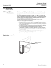
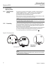
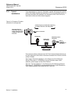
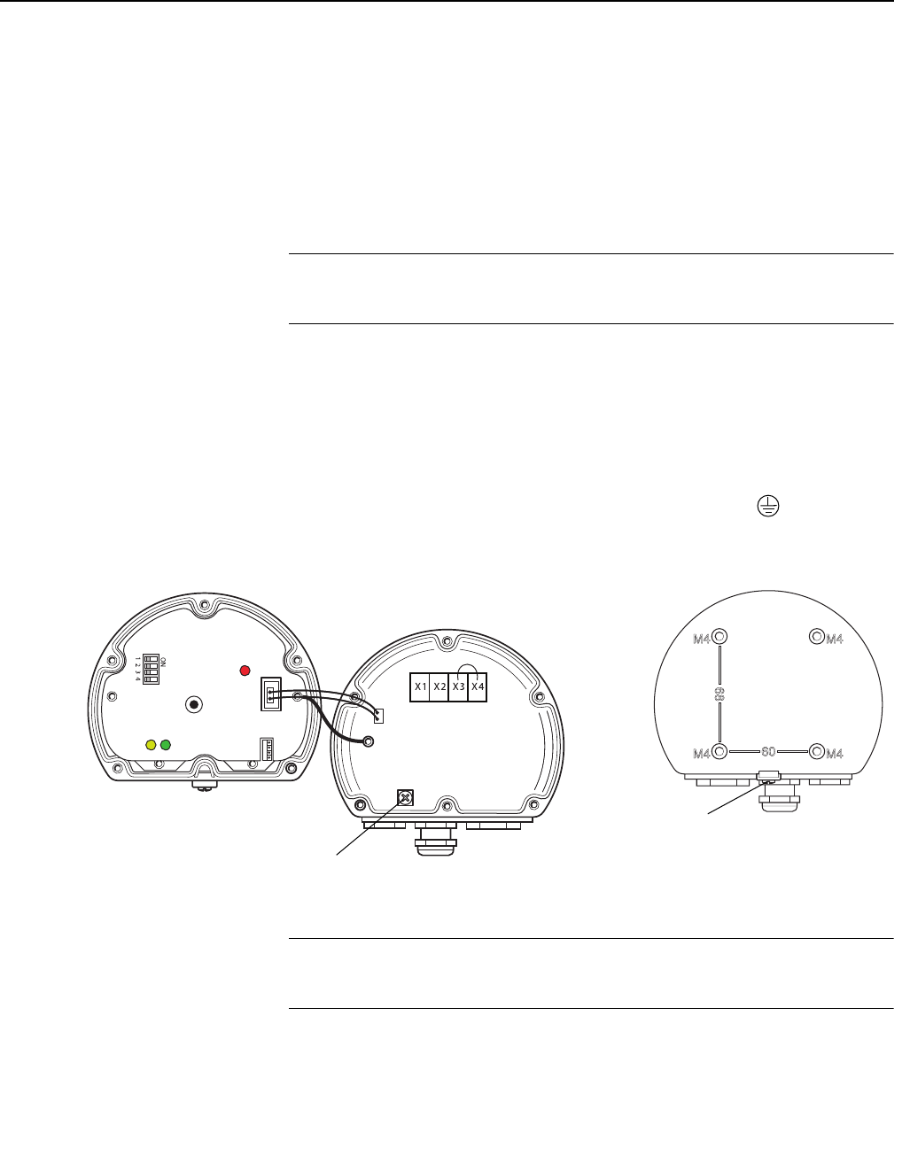
There is an external grounding screw located at the bottom of the housing and
an internal grounding screw located inside the housing, see Figure 3-3.
The internal ground screw is identified by a ground symbol: .
Figure 3-3. Grounding screws
NOTE!
When grounding the display via threaded conduit, make sure the connection
provides sufficient low impedance.
External ground
Cable diameter
minimum 4 mm
2
Internal ground


