


Reference Manual
00809-0100-2230, Rev BB
August 2014
Rosemount 2230
4-26
Section 4. Configuration and Operation
4.11.2 Application
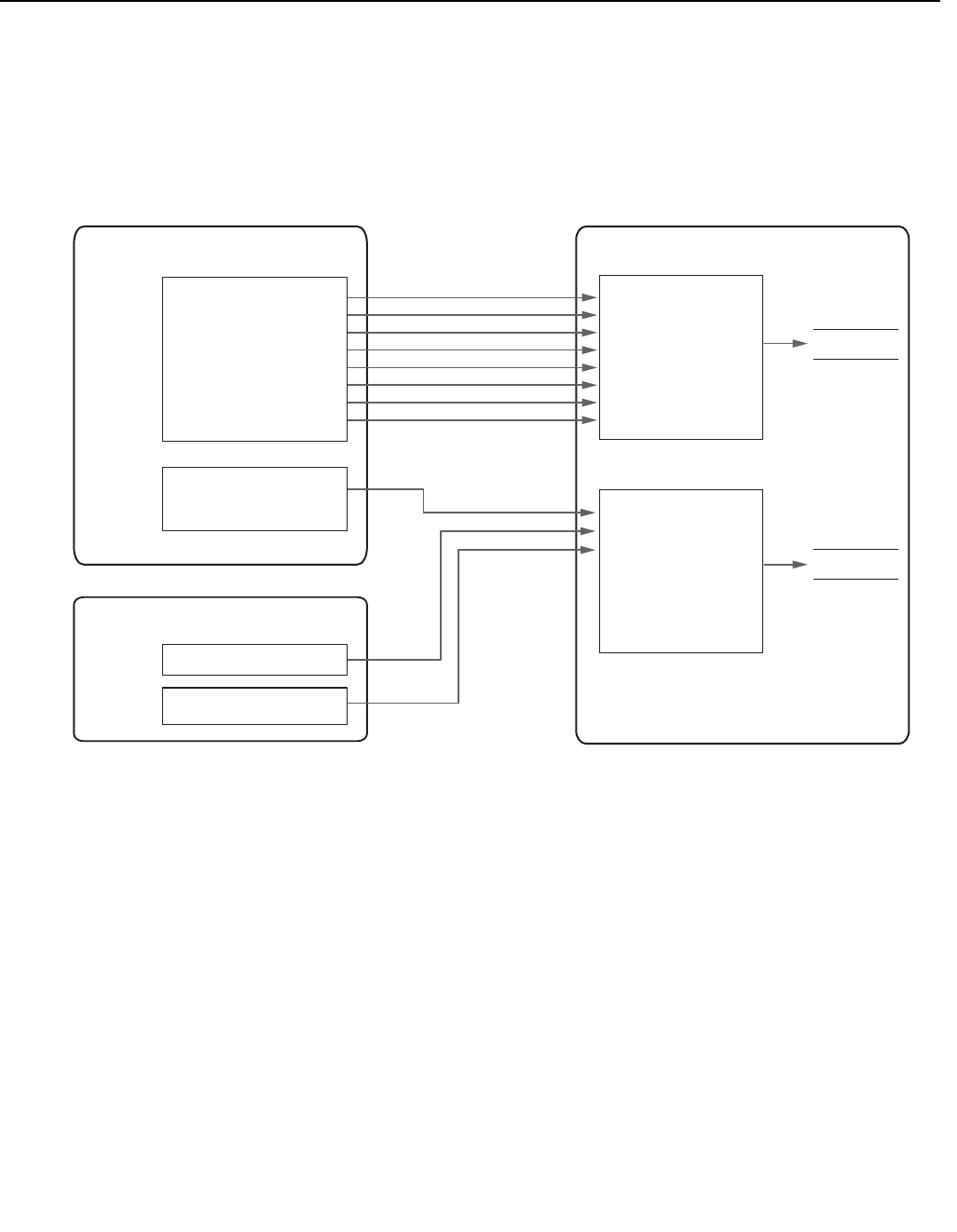
Example
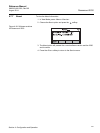
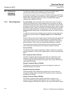
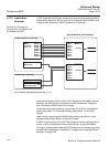
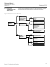
A 2230 Graphical Field Display configured for receiving level and temperature
measurement data from devices such as the Rosemount 5900S Radar Level
Gauge and the Rosemount 2240S Temperature Transmitter.
Figure 4-35. Example of a
function block configuration for
the Rosemount 2230
In the example above (Figure 4-35) a 2230 Graphical Field Display receives
data from two field devices; a Rosemount 2240S Temperature Transmitter
and a Rosemount 5900S Radar Level Gauge.
Temperature from eight elements is output from the 2240S via the Multiple
Analog Input Block 1 to the Multiple Analog Output Block 1 of the 2230
Display.
Water Level is output from the 2240S via the Analog Input Block 4 to the
Multiple Analog Output Block 2 of the 2230 Display.
A 5900S outputs product Level and Total Observed Volume via Analog Input
blocks 1 and 6 to the Multiple Analog Output Block 2 of the 2230 Display.
For output of measurement data the 2230 Display can be configured by using
the AMS Device Manager as described in “Configuration Using AMS Device
Manager” on page 4-34.
5900S Radar Level Gauge
MAO 1
2230 GRAPHICAL FIELD DISPLAY
Input 1
Input 2
Input 3
Input 4
Input 5
Input 6
Input 7
Input 8
Output 1
Output 2
Output 3
Output 4
Output 5
Output 6
Output 7
Output 8
Out
Input 1
Input 2
Input 3
Input 4
Input 5
Input 6
Input 7
Input 8
MAI 1
AI 1 (Level)
AI 6 (Total
Observed Volume)
MAO 2
Channel
Channel
AI 4
(Water Level)
Out
Out
2240S Temperature Transmitter
(Temperature
element 1-8)
MAO 1 Data
MAO 2 Data
AI <n>=factory supplied Analog Input block no. <n>