


Reference Manual
00809-0100-2230, Rev BB
August 2014
3-9
Rosemount 2230
Section 3. Installation
3.3.7 Typical
installations
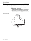
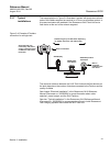
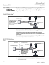
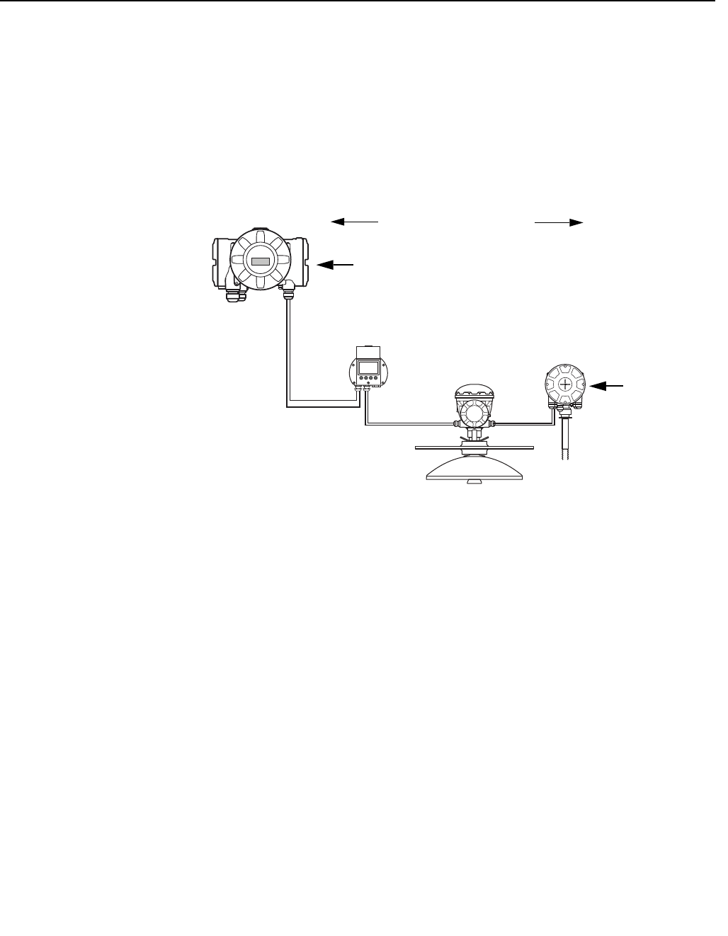
The example below in Figure 3-4 illustrates a system with terminators at both
ends of the fieldbus segment as required in a FOUNDATION fieldbus system. In
this case terminators are enabled in the Rosemount 2410 Tank Hub and a
field device at the end of the network segment.
Figure 3-4. Example of Tankbus
connection for a single tank
The maximum distance between the 2410 Tank Hub and the field devices on
the tank depends on the number of devices connected to the Tankbus and the
quality of cables.
See chapter “Electrical Installation” in the Rosemount 2410 Reference
Manual (Document no. 305030EN) for more information about cable
selection, power budget, and the 2410 Tankbus.
See also “Typical Installations” in the Rosemount 2410 Reference Manual
(Document no. 305030EN) for more examples of how to install Rosemount
Tank Gauging systems that include the 2410 Tank Hub.
Built-in terminator
Tankbus
Built-in
terminator
enabled on the
last device
2410 Tank Hub with
intrinsically safe power
supply, integrated power
conditioner, and built-in
terminator
Tankbus length up to 1000 meter depending
on number of devices and cable quality
2240S Temperature
Transmitter
5900S Radar
Level Gauge
2230 Display