97
Precautions for maintenance and
inspection
6.5.8 Inverter replacement
The inverter can be replaced with the control circuit wiring kept connected. Before replacement, remove the screws
in the wiring cover of the inverter.
1) Remove the mounting screws in both ends of the control circuit terminal block.
2) With both hands, pull down the terminal block from behind the control circuit terminals.
3) When installing the terminal block to a new inverter, exercise care not to bend the pins of the control circuit ter-
minal block connector.
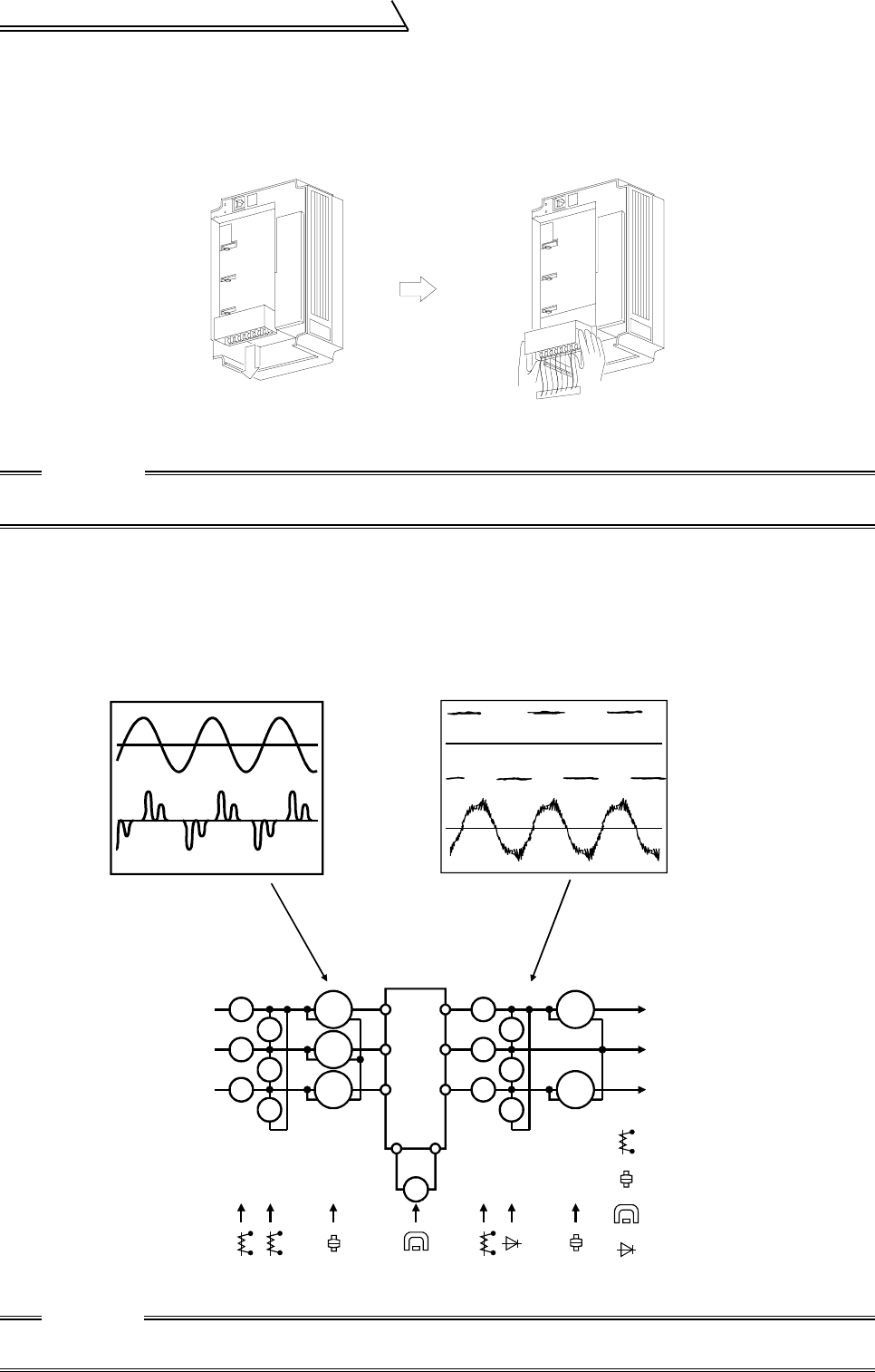
6.5.9 Measurement of main circuit voltages, currents and powers
!
Measurement of voltages and currents
Since the voltages and currents on the inverter power supply and output sides include harmonics, measurement
data depends on the instruments used and circuits measured.
When instruments for commercial frequency are used for measurement, measure the following circuits with the
instruments given on the next page.
Examples of Measuring Points and Instruments
CAUTION
Before starting inverter replacement, switch power off, wait for more than 10 minutes, and then check the
voltage with a tester and such to ensure safety.
CAUTION
Use an FFT to measure the output voltage accurately.
A tester or general measuring instrument cannot measure accurately.
+-
Ar
As
At
Vr
Vs
Vt
W11
W12
W13
Au
Av
Aw
Vu
Vv
Vw
W21
W22
V
U
V
W
3-phase 200V power input
Input voltage
Input current
Output current
3-phase
power
supply
Inverter
To motor
Instrument
types
: Moving-iron type
: Moving-coil type
: Rectifier type
Output voltage
: Electrodynamometer type
R
S
T
PN


