


12
INSTALLATION AND WIRING
2
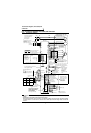
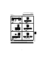
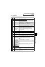
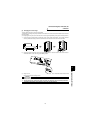
Connection diagram, PLG cable, PU
connector
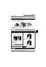
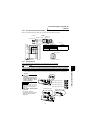
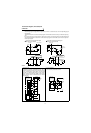
2.2.3 PLG connection cable (FR-V5CBL)
When using a dedicated motor (SF-V5R series), use a PLG cable (FR-V5CBL) for connection.
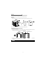
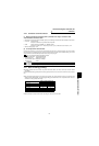
2.2.4 Setting the PLG
When a dedicated PLG cable (FR-V5CBL) is used, a setting change may not be required.
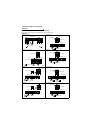
(1) Setting the power supply specification of the PLG and pulse output type
Switch the position of the jumper connector on the back surface of the control circuit terminal block according
to the PLG specification. (Refer to page 16 for removal and installation of the control circuit terminal block.)
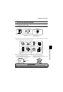
CAUTION
Make setting correctly.
Fitting the jumper connector to the position exceeding the power specification results in a PLG failure.
Fitting the jumper connector to the position below the power specification results in a PLG malfunction.
!
PLG output circuit jumper
connector
The connector is fitted to
complimentary at factory shipment.
Switch its position according to
output circuit.
L
MS3106B20-29S
Earth (Ground) wire
F-DPEVSB 12P
×
0.2mm
2
MS3057-12A
PLG side
connector
Inverter side
60
11
(Unit: mm )
FR-V500 PLG (SF-V5R)
Inverter earth (ground) terminal
PZR
PZ
PBR
PB
PAR
PA
SD
PG
G
F
D
C
B
A
R
S
2mm
2
A
B
C
D
E
K
F
G
H
J
L
M
S
N
R
P
T
MS3106B20-29S
(As viewed from wiring side)
Positioning keyway
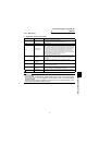
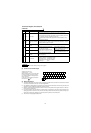
Contact us separately for other lengths.
Type Length L (m) Remarks
FR-V5CBL5 5
Standard productFR-V5CBL15 15
FR-V5CBL30 30
CAUTION
• PLG power supply jumper
connector
The connector is fitted to 12V
at factory shipment. Switch its
position according to power
supply specification.
REMARKS
Since the specification of the PLG of
the conventional motors (SF-VR, SF-
JR with PLG) is 5V, fit the jumper con-
nector to 5V.
Power supply voltage is 5.5V
Power supply voltage is 12V
Power supply voltage is 24V
Power supply voltage is external
Complimentary (CMP)
Differential line driver (LDV)
Terminating resistance
Terminating resistance