


15
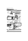
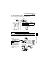
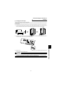
Connection diagram, PLG cable, PU
connector
* Not output during inverter reset.
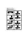
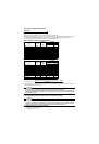
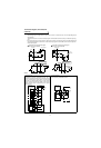
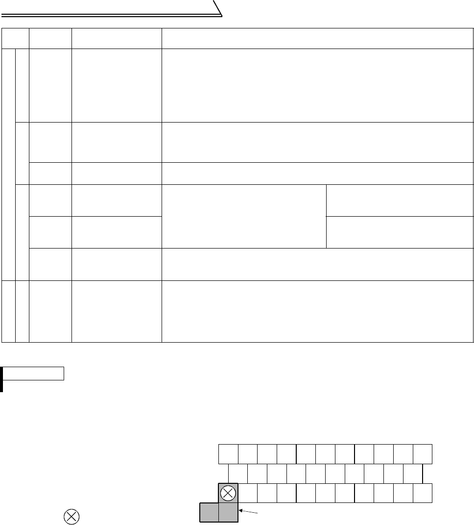
(2) Control circuit terminal layout
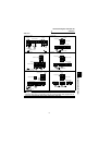
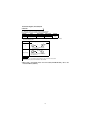
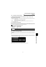
(3) Wiring instructions
1) Terminals 5, SD and SE are common to the I/O signals and isolated from each other. These common terminals
must not be connected to each other nor earthed (grounded).
2) Use shielded or twisted cables for connection to the control circuit terminals and run them away from the main
and power circuits (including the 200V relay sequence circuit).
3) Since the control circuit input signals are micro currents, use two parallel micro signal contacts or a twin con-
tact to prevent a contact fault.
4) It is recommended to use the cables of 0.75mm
2
gauge for connection to the control circuit terminals. If the
cable gauge used is 1.25mm
2
or more, the front cover may be lifted when there are many cables running or the
cables are run improperly, resulting in an operation panel or parameter unit contact fault.
5) The maximum wiring length should be 30m.
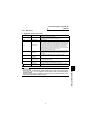
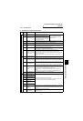
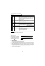
Output signals
Contact
A, B, C Alarm output
1 contact output indicating that the output has been stopped by the inverter
protective function
230VAC 0.3A, 30VDC 0.3A. Alarm: discontinuity across B-C (continuity across A-C),
Normal: continuity across B-C (discontinuity across A-C).
The terminal function varies with the output terminal function selection (Pr. 195)
setting.
Refer to page 61 for details.
Open collector
DO1 to
DO3
Digital output terminals
1 to 3
Permissible load 24VDC 0.1A
The terminal functions vary with the output terminal function selection (Pr. 190 to Pr.
192) settings. Refer to page 61 for details.
SE
Open collector output
common
Common terminal for terminals DO1, DO2 and DO3. Isolated from terminals SD and
5.
Analog
DA1 Analog signal output
One selected from the monitoring items,
such as the speed, is output.
*
The output signal is proportional to the
magnitude of the corresponding monitoring
item.
Factory setting of output item:
Speed monitoring, output signal 0 to
±10VDC, permissible load current 1mA
DA2 Analog signal output
Factory setting of output item:
Torque monitoring, output signal 0 to
10VDC, permissible load current 1mA
5
Analog signal output
common
Common terminal for DA1 and DA2.
Isolated from terminals SD and SE.
Do not earth(ground).
Communication
RS-485
– PU connector
With the PU connector, communication can be made through RS-485.
• Conforming standard : EIA Standard RS-485
• Transmission format : Multidrop link system
• Communication speed: Maximum 19200bps
• Overall length : 500m
REMARKS
For the input terminal function switchover timing, refer to page 42.
Terminal screw size: M3.5
Tightening torque : 1.2N·m
When connecting three or more control cables
to the No. 5 terminal, connect the accessory
No. 5 terminal dedicated L-shaped jumper to
the No. 5 terminal.
In this case no cable should be connected to
the screw in the part.
Type
Terminal
Symbol
Terminal Name Description
A
10E
5
3 1 PA PAR PB PBR SD OH
PC
2 DA1 SE PZ PZR PG RES
SD
BDO1DO2DI4
STF
STR
DI3 DI2 DI1
C
DO3
DA2
Jumper
5