


71
Errors (Alarms)
*
2: E. OV3 appears if the over voltage shutoff occurs during positioning.
*3. Resetting the inverter initializes the internal heat integrating data of the electronic thermal relay.
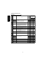
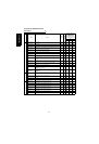
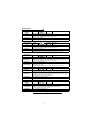
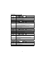
Operation Panel
Indication
E.OV1 FR-PU04V OV During Acc
Name
Regenerative overvoltage shut-off during acceleration (*2)
Description
If regenerative energy causes the inverter's internal main circuit DC voltage to reach or exceed the
specified value, the protective circuit is activated to stop the inverter output. It may also be
activated by a surge voltage generated in the power supply system.
Check point
Check for too slow acceleration.
Corrective action
• Decrease the acceleration time.
• Use the brake unit or power regeneration common converter (FR-CV) as required.
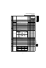
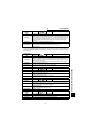
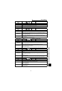
Operation Panel
Indication
E.OV2 FR-PU04V Stedy Spd OV
Name
Regenerative overvoltage shut-off during constant speed (*2)
Description
If regenerative energy causes the inverter's internal main circuit DC voltage to reach or exceed the
specified value, the protective circuit is activated to stop the inverter output. It may also be
activated by a surge voltage generated in the power supply system.
Check point
Check for sudden load change.
Corrective action
• Keep load stable.
• Use the brake unit or power regeneration common converter (FR-CV) as required.
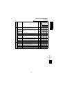
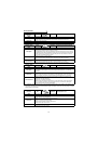
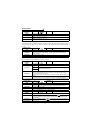
Operation Panel
Indication
E.OV3 FR-PU04V OV During Dec
Name Regenerative overvoltage shut-off during deceleration or stop
Description
If regenerative energy causes the inverter's internal main circuit DC voltage to reach or exceed the
specified value, the protective circuit is activated to stop the inverter output. It may also be
activated by a surge voltage generated in the power supply system.
Check point
Check for sudden speed reduction.
Corrective action
• Increase the deceleration time.
(Set the deceleration time that meets the inertia moment of the load)
• Decrease the braking duty.
• Use the brake unit or power regeneration common converter (FR-CV) as required.
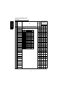
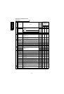
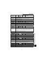
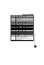
Operation Panel
Indication
E.THM FR-PU04V Motor Overload
Name
Motor overload shut-off (electronic thermal relay) (*3)
Description
The electronic thermal relay built in the inverter detects motor overheat due to overload or reduced
cooling capability during constant-speed operation to stop the inverter output. When running a
multi-pole motor or two or more motors during V/F control, provide a thermal relay in the inverter
output side since such motor(s) cannot be protected.
Protection against burnout due to motor temperature rise
Check point
Check the motor for use under overload.
Corrective action
• Reduce the load weight.
• For a constant-torque motor, set the constant-torque motor in Pr. 71 "applied motor".
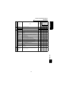
Operation Panel
Indication
E.THT FR-PU04V Inv. Overload
Name
Inverter overload shut-off (electronic thermal relay) (*3)
Description
If a current not less than 150% of the rated output current flows and overcurrent shut-off does not
occur (200% or less), inverse-time characteristics cause the electronic thermal relay to be
activated to stop the inverter output in order to protect the output transistors.
Protection of output transistors against overheat.
Check point
Check the motor for use under overload.
Corrective action
Reduce the load weight.