


14
INSTALLATION AND WIRING
2
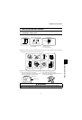
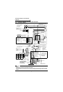
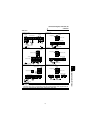
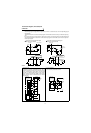
Connection diagram, PLG cable, PU
connector
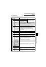
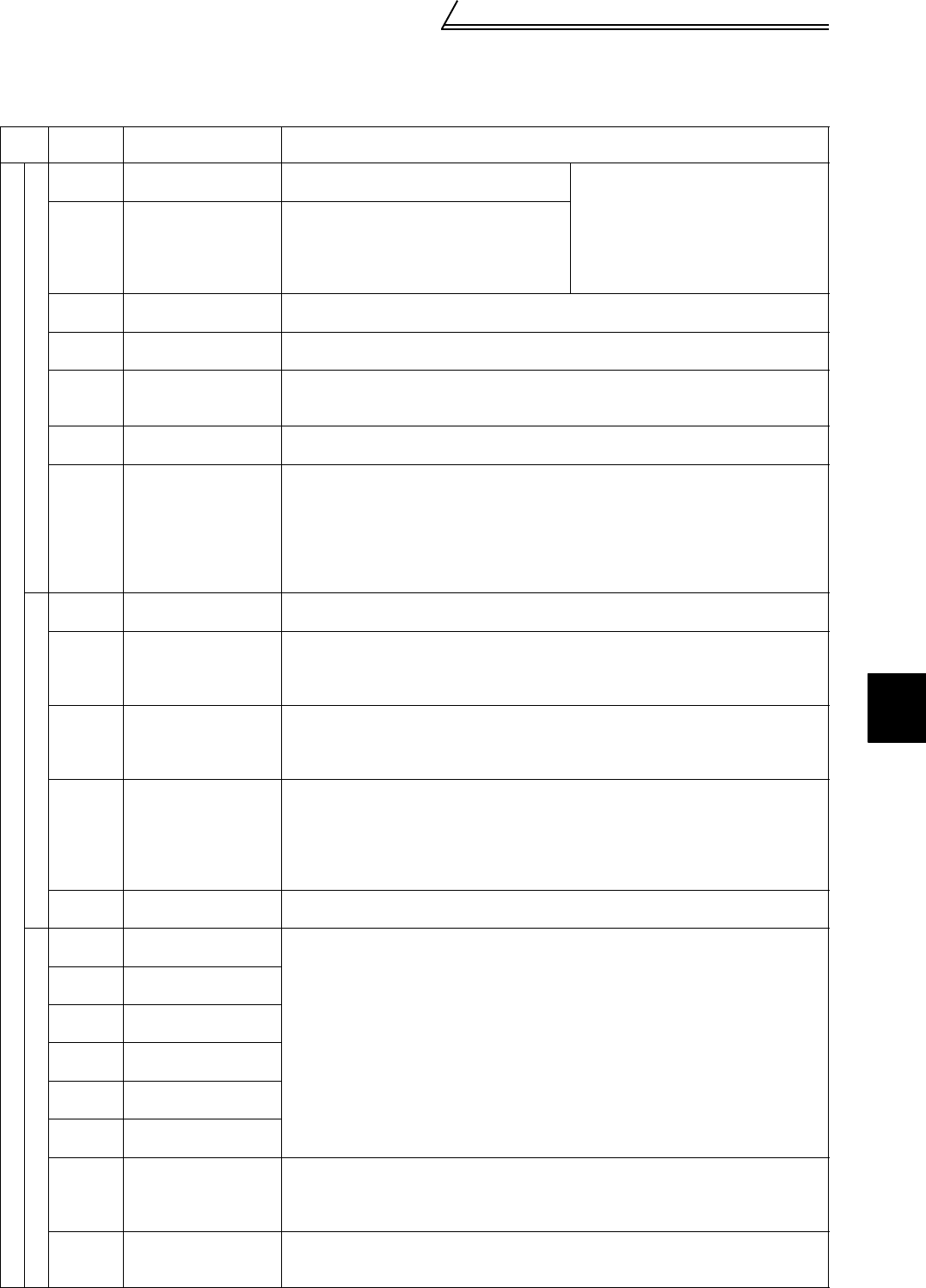
2.2.5 Control circuit
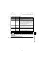
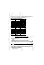
(1) Specifications of control circuit terminals
Type
Terminal
Symbol
Terminal Name Description
Input signals
Contact input
STF Forward rotation start
Turn on the STF signal to start forward
rotation and turn it off to stop.
When the STF and STR signals are
turned on simultaneously, the stop
command is given.
STR Reverse rotation start
Turn on the STR signal to start reverse
rotation and turn it off to stop.
The terminal function varies with the input
terminal function selection (Pr. 187) setting.
Refer to page 61 for details.
DI1 to DI4
Digital input
terminals 1 to 4
The terminal functions vary with the input terminal function selection (Pr. 180 to Pr.
183) settings. Refer to page 61 for details.
OH Thermal protector input
Temperature sensor terminal input for motor overheat protection.
OHT error occurs when terminals OH and SD are open.
RES Reset
Used to reset instantly. By setting Pr. 75 "reset selection", reset input possible or
reset input possible only during protective circuit operation can be selected. Turn on
the RES signal for more than 0.1s, then turn it off.
SD
Contact input common
(sink)
Common to the contact input. Common output terminal for 24VDC 0.1A power
supply (PC terminal). Isolated from terminals 5 and SE.
PC
24VDC power supply
and external transistor
common, contact input
common (source)
When connecting a transistor output (open collector output), such as a
programmable controller, connect the external power supply common for transistor
output to this terminal to prevent a malfunction caused by a sneak current.
PC-SD can be used as a 24VDC, 0.1A power supply. Note that this connection does
not prevent a sneak current.
When source logic has been selected, this terminal serves as a contact input
common.
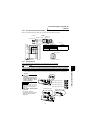
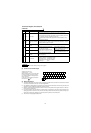
Speed setting
10E
Speed setting power
supply
10VDC, permissible load current 10mA
2 Speed setting (voltage)
By entering 0 to 10VDC, the maximum output speed is reached at 10V and I/O are
proportional. Acts as a speed command terminal for speed control or as a speed
restriction for torque control. Input resistance 10kΩ, maximum permissible voltage
20V.
3 Torque setting terminal
Acts as a torque setting signal for torque control or a torque restriction signal for
speed control and position control.
Acts as an input terminal when torque bias function by external analog is selected.
0 to ±10VDC input, input resistance 10kΩ, maximum permissible voltage ±20VDC
1
Multi-function setting
terminal
Since this is a multi-function selection terminal, its function varies with the Pr. 868
"No. 1 terminal function assignment" setting. The function of this terminal is factory-
set to adding auxiliary of speed setting terminal of terminal 2.
Refer to Pr. 868 "No. 1 terminal function assignment" in the Instruction Manual
(detailed).
0 to ±10VDC input, input resistance 10kΩ, maximum permissible voltage ±20V
5 Speed setting common
Speed setting signal (terminal 2, 1 or 3) common terminal.
Isolated from terminals SD and SE. Do not earth(ground).
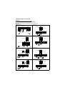
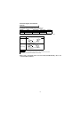
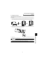
PLG signal
PA
A-phase signal input
terminal
A-, B- and Z-phase signals are input from the PLG.
The PLG jumper connector is set to complimentary when shipped from the factory.
Thus, the PLG need not be connected to PAR, PBR, and PZR.
PAR
A-phase inverted signal
input terminal
PB
B-phase signal input
terminal
PBR
B-phase inverted signal
input terminal
PZ
Z-phase signal input
terminal
PZR
Z-phase inverted signal
input terminal
PG
PLG power supply
terminal
(Positive side)
Power supply for PLG. You can switch the power supply between 5, 12 and 24VDC.
You can also switch to external power supply.
The PLG jumper connector is set to 12VDC when shipped from the factory. (Refer
to page 12.)
SD
Power supply earth
(ground) terminal
Common terminal for the PLG power supply.
Isolated from terminals 5 and SE.
Do not earth (ground).