


70
Errors (Alarms)
ERRORS AND PROTECTIVE FUNCTIONS
6
6 ERRORS AND PROTECTIVE FUNCTIONS
6.1 Errors (Alarms)
If any fault has occurred in the inverter, the corresponding protective function is activated to bring the inverter to an
alarm stop and automatically give the corresponding error (alarm) indication on the PU display.
If the fault does not correspond to any of the following errors or if you have any other problem, please contact your
sales representative or distributor.
!
When the alarm output signal holding protective function is activated, opening the magnetic contactor (MC)
provided on the inverter's power supply side will cause the control power of the inverter to be lost and the alarm
output not to be held.
!
When the alarm display protective function is activated, the operation panel display section is changed
automatically.
!
When the resetting method protective function is activated, the inverter output stop status is held, and the inverter
cannot restart unless it is reset. To reset, switch power off once, then on again, or turn on the RES signal for more
than 0.1 seconds.
If the RES signal is kept on, "Err." appears (flickers) to indicate that the inverter is in a reset status.
!
When any protective function is activated, take the corresponding corrective action, then reset the inverter, and
resume operation.
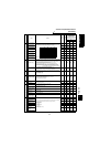
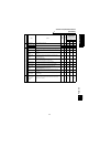
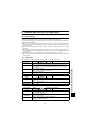
6.1.1 Major faults
When the protective function is activated, the inverter output is shut off and an alarm is output.
*
1: E. OC3 appears if the overcurrent shutoff occurs during positioning.
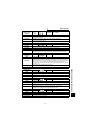
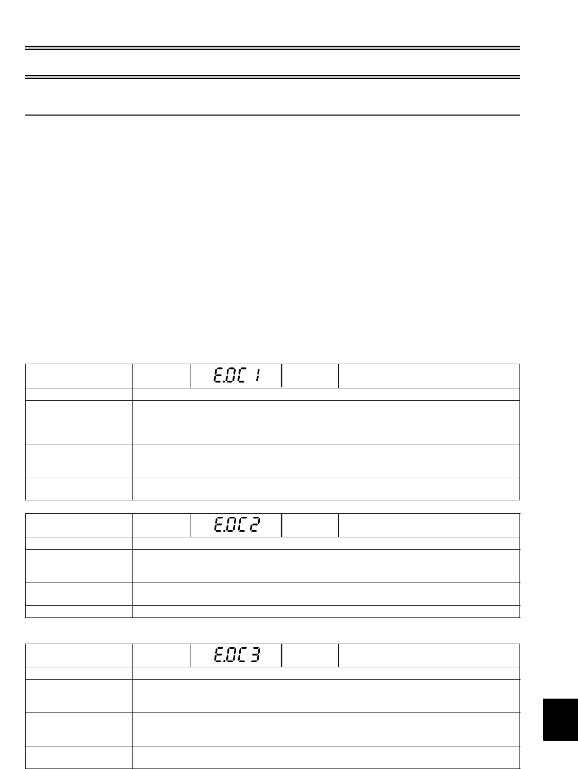
Operation Panel
Indication
E.OC1 FR-PU04V OC During Acc
Name Overcurrent shut-off during acceleration (*1)
Description
When the inverter output current reaches or exceeds approximately 200% of the rated inverter
current during acceleration, the protective circuit is activated to stop the inverter output.
Power is supplied to only the R1 and S1 terminals. This indication also appears when the start
signal is entered.
Check point
• Check for sudden acceleration.
• Check for output short circuit.
• Check that main circuit power (R, S, T) is supplied.
Corrective action
• Increase the acceleration time.
• Supply main circuit power (R, S, T).
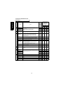
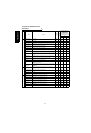
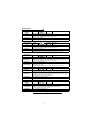
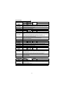
Operation Panel
Indication
E.OC2 FR-PU04V Stedy Spd OV
Name
Overcurrent shut-off during constant speed (*1)
Description
When the inverter output current reaches or exceeds approximately 200% of the rated inverter
current during constant speed operation, the protective circuit is activated to stop the inverter
output.
Check point
• Check for sudden load change.
• Check for output short circuit.
Corrective action
Keep load stable.
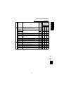
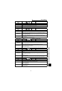
Operation Panel
Indication
E.OC3 FR-PU04V OC During Dec
Name
Overcurrent shut-off during deceleration
Description
When the inverter output current reaches or exceeds approximately 200% of the rated inverter
current during deceleration (other than acceleration or constant speed), the protective circuit is
activated to stop the inverter output.
Check point
• Check for sudden speed reduction.
• Check for output short circuit.
• Check for too fast operation of the motor's mechanical brake.
Corrective action
• Increase the deceleration time.
• Check the mechanical brake operation.