


21
Precautions for use of the vector inverter
2.4 Precautions for use of the vector inverter
The FR-V500 series is a highly reliable product, but incorrect peripheral circuit making or operation/handling
method may shorten the product life or damage the product.
Before starting operation, always recheck the following items.
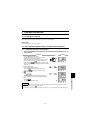
(1) Use insulation-sleeved crimping terminals for the power supply and motor cables.
(2) Power must not be applied to the output terminals (U, V, W) of the inverter. Otherwise the inverter will be damaged.
(3) After wiring, wire off-cuts must not be left in the inverter.
Wire off-cuts can cause an alarm, fault or malfunction. Always keep the inverter clean.
When drilling mounting holes in a control box or the like, use care not to allow chips etc. to enter the inverter.
(4) Wire the cables of the recommended size to make a voltage drop 2% or less.
If the wiring distance is long between the inverter and motor, a main circuit cable voltage drop will cause the
motor torque to decrease especially at the output of a high frequency.
Refer to page 11 for the recommended wire sizes.
(5) The overall wiring length should be 100m maximum.
Especially for long distance wiring, the fast-response current restriction function may be reduced or the equip-
ment connected to the secondary side may malfunction or become faulty under the influence of a charging cur-
rent due to the stray capacity of the wiring. Therefore, note the overall wiring length.
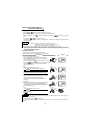
(6) Electromagnetic wave interference
The input/output (main circuit) of the inverter includes harmonic components, which may interfere with the communi-
cation devices (such as AM radios) used near the inverter. In this case, install the optional FR-BIF radio noise filter
(for use in the input side only) or FR-BSF01 or FR-BLF line noise filter to minimize interference.
(7) Do not install a power factor correction capacitor, surge suppressor or radio noise filter (FR-BIF option) in the
output side of the inverter.
This will cause the inverter to trip or the capacitor and surge suppressor to be damaged. If any of the above devices is
installed, immediately remove it. (When the FR-BIF radio noise filter is connected, switching power off during motor
operation may result in E. UVT. In this case, connect the radio noise filter in the primary side of the magnetic contactor.)
(8) When rewiring after operation, switch power off, wait for more than 10 minutes, and then make sure that the
voltage is zero using a tester, etc. For some time after power-off, there is a dangerous voltage in the capacitor.
(9) A short circuit or earth (ground) fault in the inverter output side may damage the inverter modules.
• Fully check the insulation resistance of the circuit prior to inverter operation since repeated short circuits
caused by peripheral circuit inadequacy or an earth (ground) fault caused by wiring inadequacy or reduced
motor insulation resistance may damage the inverter modules.
• Fully check the to-earth (ground) insulation and inter-phase insulation of the inverter secondary side before power-on.
Especially for an old motor or use in hostile atmosphere, securely check the motor insulation resistance etc.
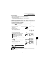
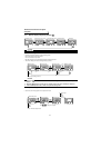
(10) Do not use the inverter power supply side magnetic contactor to start/stop the inverter.
Always use the start signal (turn on/off terminals STF, STR-SD) to start/stop the inverter. (Refer to page 7.)
(11) Across the P and PR terminals, connect only an external regenerative brake discharge resistor.
Do not connect a mechanical brake.
(12) Do not apply a voltage higher than the permissible voltage to the inverter I/O signal circuits.
Application (contact) of a voltage higher than the permissible voltage to the inverter I/O signal circuits or oppo-
site polarity may damage the I/O devices. Especially check the wiring to prevent the speed setting potentiome-
ter from being connected incorrectly to short terminals 10E-5.
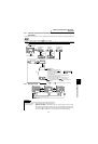
(13) Use of single-phase power supply
Do not use single-phase power input.
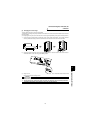
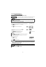
(14) Precautions for use of any motor other than the dedicated motor (SF-V5R) or standard motor with PLG (SF-
JRwith PLG)
a)Vector control cannot be exercised without PLG.
b)Connect the PLG directly to the backlash-free motor shaft.
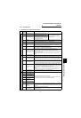
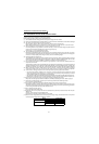
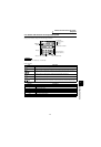
(15) Since the rated voltage differs from the commercial power supply voltage, the dedicated motor cannot perform
commercial power supply-inverter switchover operation.
Motor Rated Voltage
SF-V5R
3.7kW or less 170V
5.5kW or more 160V
SF-V5RH
3.7kW or less 340V
5.5kW or more 320V