


57
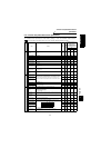
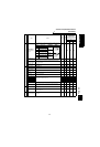
PARAMETERS
Function list (Extended function
parameters)
Operation selection functions
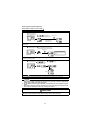
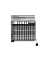
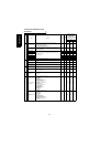
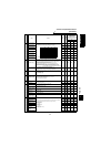
71 Applied motor
Set the motor to be used.
0, 3 to 8, 10, 13 to 18, 20, 23, 24, 30, 33, 34
30
"
""
""
""
""
""
"
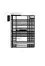
72
PWM frequency
selection
1 to 6 1
"
""
""
""
""
""
"
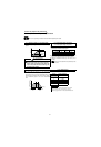
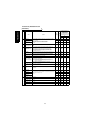
73 Speed setting signal
You can set the input specifications of terminals 1 and 2 and whether to use the
override function or not.
0
"
""
""
""
"
×
Function
Parameter
Name Outline
Factory
Setting
Cus-
tomer
Set-
ting
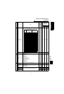
At-a-glance Guide to Func-
tions
"
""
": Usable function
×: Unusable function
* :
Functions that can be used
for parameter-set position con-
trol
Vector Control
Speed
control
Torque
control
Position
control
Setting Motor Control Constants
0
Standard motor
(SF-JR etc.)
Inverter internal constants
3 Offline auto tuning
4 Offline auto tuning data utilization
5 Star connection direct input
6 Delta connection direct input
7 Star connection direct input + offline auto tuning
8 Delta connection direct input + offline auto tuning
10
Constant-torque motor
(SF-HRCA etc.)
Inverter internal constants
13 Offline auto tuning
14 Offline auto tuning data utilization
15 Star connection direct input
16 Delta connection direct input
17 Star connection direct input + offline auto tuning
18 Delta connection direct input + offline auto tuning
20
SF-JR(4P)-1.5kW or
less
Inverter internal constants
23 Offline auto tuning
24 Offline auto tuning data utilization
30
(factory
setting)
SF-V5R vector control
inverter motor (including
SF-VR type motor)
Inverter internal constants
33 Offline auto tuning
34 Offline auto tuning data utilization
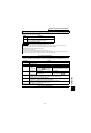
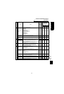
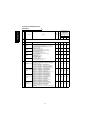
*1 The value of terminal 1 (speed setting auxiliary input) is added to the main speed
setting signal of terminal 2.
*2 When override has been selected, terminal 1 acts as the main speed setting and
terminal 2 acts as the override signal (50 to 150% at 0 to 10V).
*3 When "30" or "31" is set in Pr. 128, terminal 2 acts as the PID set point function.
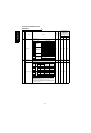
*4 When override has been selected, terminal 1 acts as speed restriction and terminal
2 acts as the override signal.
Pr. 73
Setting
Control
Mode
Function
Terminal 1
(0 to ±10V)
Terminal 2
(0 to 10V)
*3
Override
Polarity
reversible
0
Speed
control
××
Addition auxiliary
*1
Speed command
Main speed setting
4
"
*2
× Main speed setting Override signal
10 × "
Addition auxiliary
*1
Speed command
Main speed setting
14
"
*2
" Main speed setting Override signal
0
Tor qu e
control
××
Addition auxiliary
Speed restriction
Speed restriction
4
"
*4
× Speed restriction Override signal
10 ××
Addition auxiliary
Speed restriction
Speed restriction
14
"
*4
× Speed restriction Override signal
0, 4, 10,
14
Position
control
No function No function No function