


72
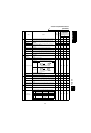
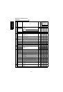
Errors (Alarms)
ERRORS AND PROTECTIVE FUNCTIONS
6
*
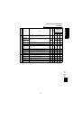
4: When an instantaneous power failure occurs, the alarm display and alarm output are not provided, but the
inverter performs protective operation to prevent a fault from occurring in itself. In some operating status (load
magnitude, acceleration/deceleration time setting, etc.), overcurrent or other protection may be activated upon
power restoration.
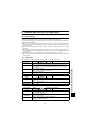
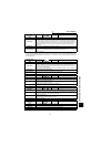
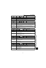
Operation Panel
Indication
E.IPF FR-PU04V Inst. Pwr. Loss
Name
Instantaneous power failure protection (*4)
Description
If a power failure occurs for longer than 15ms (this also applies to inverter input shut-off), the
instantaneous power failure protective function is activated to stop the inverter output in order to
prevent the control circuit from malfunctioning. At this time, the alarm warning output contacts open
(across terminals B-C) and close (across terminals A-C). If a power failure persists for longer than
100ms, the alarm warning output is not provided, and the inverter restarts if the start signal is on
upon power restoration. (The inverter continues operating if an instantaneous power failure is
within 15ms.)
Check point
Find the cause of instantaneous power failure occurrence.
Corrective action
• Remedy the instantaneous power failure.
• Prepare a backup power supply for instantaneous power failure.
• Set the function of automatic restart after instantaneous power failure (Pr. 57).
(Refer to page 56.)
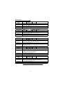
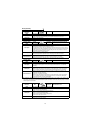
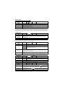
Operation Panel
Indication
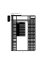
E.UVT FR-PU04V Under Voltage
Name
Undervoltage protection
Description
If the power supply voltage of the inverter reduces, the control circuit will not perform normal
functions. In addition, the motor torque wiil be insufficient and/or heat generation will increase. To
prevent this, if the power supply voltage reduces below about 150V (300V for the 400V class), this
function stops the inverter output.
When a jumper is not connected across P-P1, the undervoltage protective function is activated.
Check point
• Check for start of large-capacity motor.
• Check that a jumper or DC reactor is connected across terminals P-P1.
Corrective action
Check the power supply system equipment such as power supply.
Connect a jumper or DC reactor across terminals P-P1.
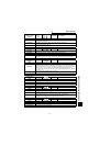
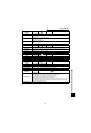
Operation Panel
Indication
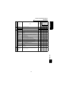
E.FIN FR-PU04V H/Sink O/Temp
Name
Fin overheat
Description
If the heatsink overheats, the temperature sensor is actuated to stop the inverter output.
Check point
• Check for too high ambient temperature.
• Check for heatsink clogging.
• Check that the cooling fan is stopped.
Corrective action
• Set the ambient temperature to within the specifications.
• Replace the cooling fan.
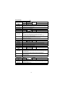
Operation Panel
Indication
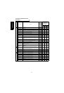
E.BE FR-PU04V Br. Cct. Fault
Name
Brake transistor alarm detection
Description
This function stops the inverter output if an alarm occurs in the brake circuit, e.g. damaged brake
transistors.
In this case, the inverter must be powered off immediately.
Check point
• Reduce the load inertia.
• Check that the frequency of using the brake is proper.
• Check that the brake resistor selected is correct.
Corrective action
Replace the inverter.
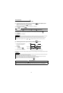
Operation Panel
Indication
E.GF FR-PU04V Ground Fault
Name
Output side earth (ground) fault overcurrent protection
Description
This function stops the inverter output if an earth (ground) fault overcurrent flows due to an earth
(ground) fault that occurred in the inverter's output (load) side.
Check point
Check for an earth (ground) fault in the motor and connection cable.
Corrective action
Remedy the earth (ground) fault portion.