


42
CONTROL
4
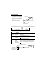
Control mode switchover timing
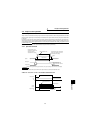
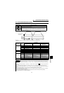
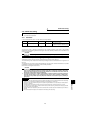
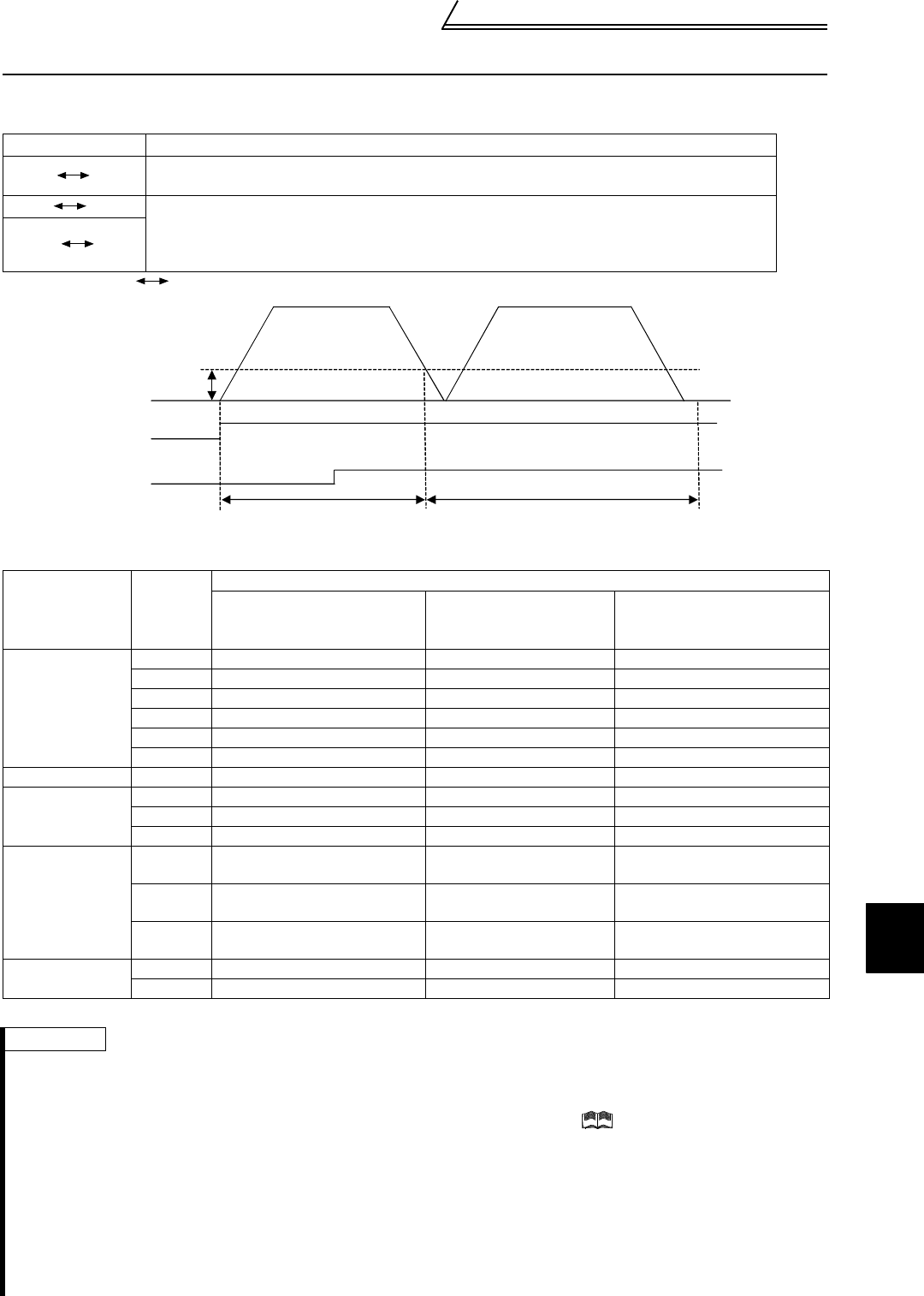
4.4 Control mode switchover timing
Depending on a parameter setting change or whether the MC terminal turns on/off, the control mode switches at the
following timing.
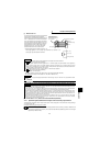
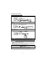
〈
Example: Speed
Position, when Pr. 800 = 4
〉
!
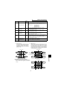
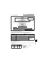
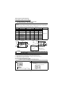
Terminals and terminal functions changed by control mode switchover
The terminal functions vary with the control mode as indicated in the following table.
*: Assumes that the Pr. 868 value is the factory setting.
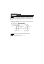
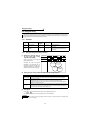
Switchover Pattern
Switchover Operation
Speed Torque
The mode can be changed any time independently of whether the motor is at a stop or running
or the DC brake (servo lock) is operating.
Speed Position
The mode can be changed when the speed is equal to or lower than the low speed detection level.
When the speed is higher than the low speed detection level, changing the MC signal during
rotation will not switch the control mode to the other, and as soon as the speed falls to or below Pr.
865 "low speed detection level", the control mode is changed according to the terminal status.
Position Torque
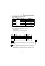
Classification
Terminal
Name
Description
Speed Control Torque Control
Speed Control/Torque Con-
trol Switchover
(MC:ON/OFF)
Contact input
signal
STF Forward rotation command ←←
STR Reverse rotation command ←←
DI1 Multi-function input 1 ←←
DI2 Multi-function input 2 ←←
DI3 Multi-function input 3 ←←
DI4 Multi-function input 4 ←←
Contact output ABC Alarm contact ←←
Open collector
output
DO1 Multi-function output 1 ←←
DO2 Multi-function output 2 ←←
DO3 Multi-function output 3 ←←
Analog input
2 Speed command input Speed restriction input
Speed command/speed
restriction
1*
Speed command
auxiliary input
Speed restriction
auxiliary input
Speed command/speed
restriction
3 Torque restriction input Torque command input
Torque restriction/torque
command
Analog output
DA1 Multi-function monitor output 1 ←←
DA2 Multi-function monitor output 2 ←←
REMARKS
• DI1 to DI4, STR terminal function selection ⇒ Pr. 180 to Pr. 183, Pr. 187 (input terminal function selection). (Refer to page 61.)
• DO1 to DO3, ABC terminal function selection ⇒ Pr. 190 to Pr. 192, Pr. 195 (output terminal function selection). (Refer to page
61.)
• No. 1 terminal function selection ⇒ Pr. 868 "No. 1 terminal function assignment" ( Refer to the Instruction Manual
(detailed).)
• No. 1, 2, 3 terminal bias/gain adjustment ⇒ Pr. 902 to Pr. 905, Pr. 917, Pr. 918 (bias/gain adjustment) (Refer to page 47.)
• DA1, DA2 terminal function selection ⇒ Pr. 54, Pr. 158 (DA1, DA2 function selection) (Refer to page 56 (DA1) and page 60
(DA2).)
• DA1, DA2 terminal calibration ⇒ Pr. 900, Pr. 901 (DA1, DA2 terminal calibration) (Refer to page 25.)
• MC signal terminal assignment ⇒ Set "26" to any of DI1 to DI4 and STR using any of Pr. 180 to Pr. 183 and Pr. 187 (input ter-
minal function selection). (Refer to page 61.)
• For the change in terminals and terminal functions during position control, refer to the Instruction Manual (detailed).
• Control system selection ⇒ Pr. 800 (Refer to page 53.)
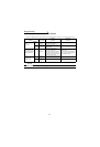
MC
STF
Low speed detection
level (Pr. 865)
Speed control Position control