


83
Troubleshooting
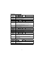
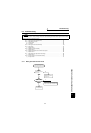
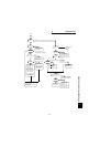
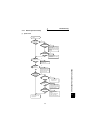
6.4.2 Motor does not rotate
(1) Vector contro
l
N
Y
2
1
Y
Y
Y
N
Y
N
Y
N
N
Y
Y
Y
Y
N
N
N
N
Y
N
N
N
Y
Y
Y
N
N
Y
N
Y
Y
Y
Y
Y
Y
N
N
N
N
The motor does
not rotate.
Perform wiring correctly.
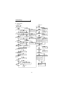
Turn off the MRS and RES signals.
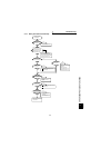
Make the maximum setting
correctly.
Open the brake.
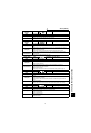
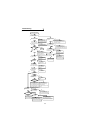
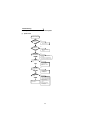
Is the speed
command input?
Is an analog input used?
Is an analog input used?
Apply a voltage to the
analog input terminals
(across 3-5). Also, to
calibrate the No. 3 terminal,
adjust the bias and gain of
the analog voltage using
Pr. 904 and Pr. 905.
Input the speed command.
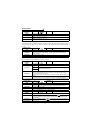
Set the torque restriction.
(Setting using parameters)
Set the torque restriction
(Pr. 810 to Pr. 817).
Are the charge lamp on
and the operation panel
LED indication given?
There is no alarm output
to the operation panel
Is the secondary side wiring
(U, V, W) of the inverter
correct without open cables?
Is the start command
input?
Are the MRS and
RES signals both off?
Is the maximum frequency
(Pr. 1) other than 0?
Is reverse rotation prevention
(Pr. 78) set to enable rotation
in the rotation direction?
When the electromagnetic
brake is used, is the
electromagnetic
brake open?
Is operation performed
without using
communication?
Is speed control
exercised?
Pr.800
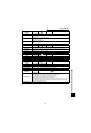
Check the alarm definition,
remove the cause of the alarm,
and reset the inverter.
PU: Press FWD (REV).
External: Turn on STF (STR).
Also check that both STF and
STR are not on.
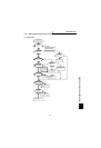
Is any cable open?
Are the station number
and so on set correctly?
Please contact your sales
representative.
Wire the cables correctly.
Make communication setting.
Are the operation
panel LED off and
the charge lamp on?
Are the operation
panel LED on and
the charge lamp off?
Are the earth leakage
breaker and magnetic
contactor on?
Turn on the earth leakage
breaker and magnetic contactor.
Check for a low voltage, phase
failure, poor connection, etc.
and take corrective action.
Is an external
command used for the
speed command?
Apply a voltage to the
analog input terminals
(*across 2-5).
Also, to calibrate the No. 2
terminal, adjust the bias and
gain of the analog voltage
using Pr. 902 and Pr. 903.
*No. 1 terminal depending
on the setting of Pr. 73,
Pr. 868 or Pr. 805
Is the torque restriction
command input?
Is an external command
used for torque restriction?
Turn on the multiple
speed (*RH, RM, RL,
REX).
*The terminal functions
vary with input terminal
assignment (Pr. 180 to
Pr. 183, Pr. 187).
Set the torque restriction.
N
Y
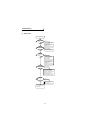
Are the PLG types and
rotation direction correct?
Is the connection correct?
Check the PLG rotation direction.
Check the connection
Set reverse rotation prevention
(Pr. 78) correctly.
Speed
Torque
N
Set the speed from the PU.
N
Set "20" (V/F control) in Pr. 800 and
operate in V/F control.
(For trouble shooting in V/F control,
2) Connect a jumper or DC
reactor.
Y
N
Is the speed command
higher than the start
speed?
Set the speed command
higher than the Pr. 13
"start speed" value.
1) The jumper across P-P1 or
DC reactor is disconnected.
Are the voltages of the
main circuit power supply
voltage terminals (R, S,
T) normal?
2) Control power is not supplied.
1) Contact fault of the operation
panel
(Check whether jumpers are
connected across R-R1 and
S-S1.)
(Refer to page 33)
(Refer to page 33.)
Page 84
refer to page 85)
Page 84