


33
Speed control operation
4.1.4 Operation command setting
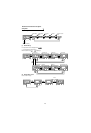
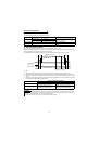
(1) Forward and reverse rotation commands (terminals STF, STR)
1)Command from the operation panel (FR-DU04
-1
): Turn on or (Refer to page 22.).
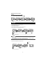
2)External command: Turn the forward/reverse rotation command (terminal STF, STR)on. (Refer to page 23.)
(Turning both terminals STF and STR on or off will give a stop command.)
(2) Speed command
1)Operation panel (FR-DU04
-1
) speed setting (Refer to page 22.)
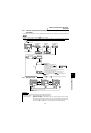
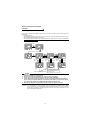
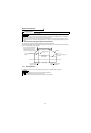
2)External analog command (terminal 2 (or terminal 1))
Give a speed command using the analog signal input to terminal 2 (or terminal 1).
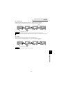
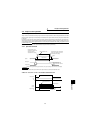
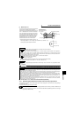
3)Multi-speed commands
The external signals (RH, RM, RL) may also be used to give speed command.
(The terminals are factory-set as follows. DI1 = RH, DI2 = RM, DI3 = RL)
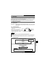
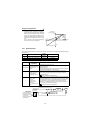
4.1.5 Torque restriction
Select the setting method of output torque restriction during speed control from among the external analog input
terminal "3" or "1" (Pr. 868 "No.1 terminal function selection" = "2") or parameter settings using Pr. 810 "torque
restriction mode".
Torque restriction is factory-set to exercise by parameter settings, and the restriction level is 150%.
REMARKS
Use Pr. 79 "operation mode" to change the operation mode between operation panel (PU) and external command
(EXT). (Refer to page 52.)
REMARKS
Use Pr. 79 "operation mode selection" to change the operation mode between operation panel (PU) and external
command (EXT). (Refer to page 52.)
REMARKS
• Set Pr. 73 "speed setting signal" to change between the main speed and override of terminal 2.
( Refer to the Instruction Manual (detailed)).
• For the adjustment of bias/gain of analog signal, set terminal 2 in Pr. 902 "speed setting No. 2 bias" or Pr. 903
"speed setting No. 2 gain". (Refer to page 47.)
• The function of terminal 1 changes according to the setting of Pr. 868 "terminal 1 function selection". For the factory
set function of terminal 1, refer to the Instruction Manual(detailed). The function of this terminal is factory-set to add-
ing auxiliary of the speed setting signal of terminal 2.
• Set the adjustment of bias/gain of terminal 1 in Pr. 917 "No. 1 terminal bias (speed)" or Pr. 918 "No. 1 terminal gain (speed)".
REMARKS
• The RH, RM and RL signals are assigned to terminals DI1 to DI4 and STR using Pr. 180 to Pr. 183 and Pr. 187
(input terminal function selection).
• Speed control has the following priority:
maximum setting > Jog >speed jump> minimum setting > 12 bit digital (FR-A5AX) /16 bit digital (FR-V5AH) > 16 bit
digital (FR-V5AH) > multi-speed > option high-resolution output (FR-V5AX) > PID control > analog input
CAUTION
When the speed command is to be given using the analog command (terminal 2), turn off the external sig-
nals (RH, RM, RL). If any of external signals (RH, RM, RL) is on, the multi-speed commands are made valid.
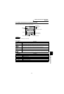
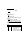
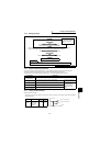
Parameter Name
Factory
Setting
Description
803
Constant output region
torque characteristic
selection
0
0: Motor output is made constant (torque is reduced)
1: Torque is made constant
You can select whether the torque restriction in the constant output
region to be constant torque restriction or constant output restriction.
(Refer to page 38.)
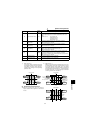
810
Torque restriction input
method selection
0
0: Internal torque restriction (torque restriction by parameter settings)
(Refer to page 34)
1: External torque restriction (torque restriction using No. 3 and No. 1
(option (FR-V5AX) No. 6 terminal))
With the upper limit of torque restriction as set in Pr. 22, Pr. 812, Pr. 813
and Pr. 814, the analog input from the No. 3 terminal input is used as
the torque restriction value on the driving side within the Pr. 22 setting
range. When regenerative torque restriction is assigned to the No. 1
terminal or option's No. 6 terminal on the regenerative side, the analog
input from the No. 1 terminal or No. 6 terminal is used as the torque
restriction.
FWD
REV