


94
Precautions for maintenance and
inspection
ERRORS AND PROTECTIVE FUNCTIONS
6
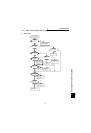
6.5.5 Pressure test
Do not conduct a pressure test. Deterioration may occur.
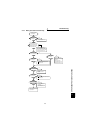
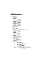
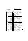
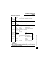
6.5.6 Daily and periodic inspection
Area of
Inspection
Inspection
Item
Description
Interval
Method Criterion Instrument
Customer’s
check
Daily
Periodic*
1 year
2 years
General
Surrounding
environment
Check ambient
temperature, humidity,
dust, dirt, etc.
"
Measure 5cm away from
the inverter.
(Refer to page 6.)
Ambient
temperature: -10°C
to +50°C , non-
freezing.
Ambient humidity:
90% or less, non-
condensing.
Thermometer,
hygrometer,
recorder
Overall unit
Check for unusual
vibration and noise.
"
Visual and auditory
checks.
No fault.
Power supply
voltage
Check that the main
circuit voltages are
normal.
"
Measure voltages
across the inverter
terminal block R, S and
T phases.
Within permissible
AC (DC) voltage
fluctuation (refer to
page 99)
Tester, digital
multimeter
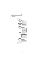
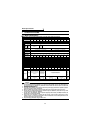
Main circuit
General
(1) Check with megger
(across main circuit
terminals and earth
(ground) terminal).
(2) Check for loose
screws and bolts.
(3) Check for overheat
traces on the parts.
(4) Clean.
"
"
"
"
(1) Disconnect all cables
from the inverter and
measure across
terminals R, S, T, U,
V, W and earth
terminal with
megger.
(2) Retighten.
(3) Visual check.
(1) 5MΩ or more.
(2), (3) No fault.
500VDC
class megger
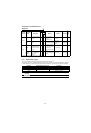
Conductors,
cables
(1) Check conductors
for distortion.
(2) Check cable
sheaths for
breakage.
"
" (1), (2) Visual check. (1), (2) No fault.
Terminal block Check for damage. " Visual check No fault
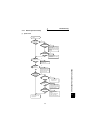
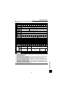
Relay
(1) Check for chatter
during operation.
(2) Check for rough
surface on contacts.
"
"
(1) Auditory check.
(2) Visual check.
(1), (2) No fault.
Resistor
(1) Check for crack in
resistor insulation.
(2) Check for open
cable.
"
"
(1) Visual check.
Cement resistance,
wire-wound resistor.
(2) Disconnect one end
and measure with
tester.
(1) No fault.
(2) Indication
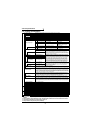
Control cir-
cuit
Protective
circuit
Operation
check
(1) Check balance of
output voltages
across phases with
the inverter
operated alone.
(2) Perform sequence
protective operation
test to ensure no
fault in protective
and display circuits.
"
"
(1) Measure voltages
across the inverter
output terminals U-
V-W.
(2) Simulatively short or
open the protective
circuit output
terminals of the
inverter.
(1) Phase-to-phase
voltage balance
within 4V (8V) for
200V (400V).
(2) Fault must occur
because of
sequence.
Digital
multimeter,
rectifier type
voltmeter
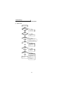
Cooling
system
Cooling fan
(1) Check for unusual
vibration and noise.
(2) Check for loose
connection.
"
""
"
(1) Turn by hand with
power off.
(2) Visual check.
No unusual vibration
and noise.