98
Precautions for maintenance and
inspection
ERRORS AND PROTECTIVE FUNCTIONS
6
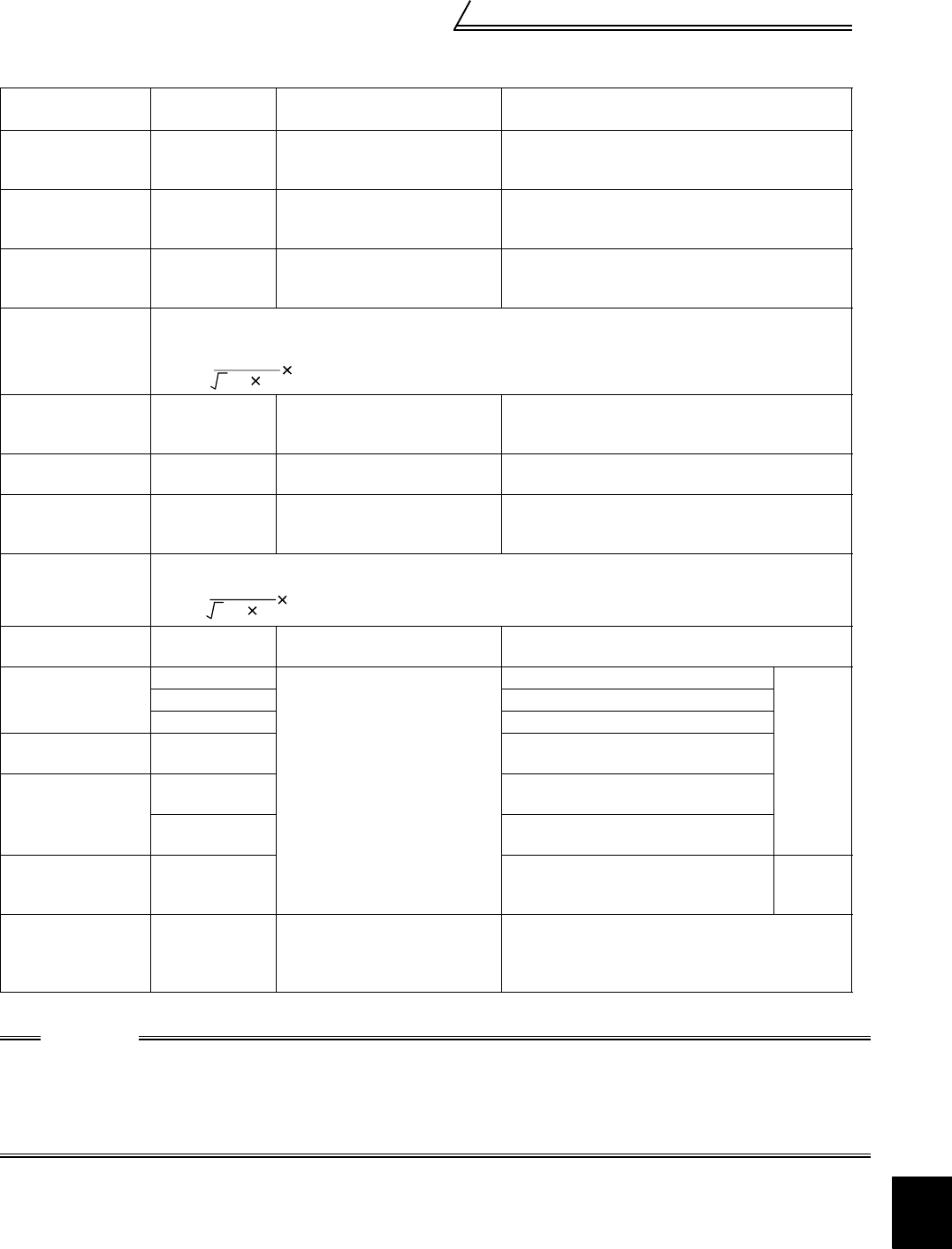
Measuring Points and Instruments
Item
Measuring
Point
Measuring Instrument Remarks (Reference Measurement Value)
Power supply
voltage
V1
Across R-S, S-T
and T-R
Moving-iron type AC voltmeter
Within permissible commercial power supply AC
voltage fluctuation (Refer to page 98)
Power supply side
current
I1
R, S and T line
currents
Moving-iron type AC ammeter
Power supply side
power
P1
At R, S and T,
and across R-S,
S-T and T-R
Electrodynamic type single-
phase wattmeter
P1=W11+W12+W13 (3-wattmeter method)
Power supply side
power factor
Pf1
Calculate after measuring power supply voltage, power supply side current and power supply side
power.
Output side voltage
V2
Across U-V, V-
W and W-U
Rectifier type AC voltmeter
(Caution 1)
(Moving-iron type cannot measure)
Difference between the phases is within ±1% of
the maximum output voltage.
Output side current
I2
U, V and W line
currents
Moving-iron type AC ammeter
(Caution 2)
Difference between the phases is 10% or lower of
the rated inverter current.
Output side power
P2
At U, V and W,
and across U-V
and V-W
Electrodynamic type single-
phase wattmeter
P
2
=W
21
+W
22
2-wattmeter method (or 3-wattmeter method)
Output side power
factor
Pf2
Calculate in similar manner to power supply side power factor.
Converter output Across P-N
Moving-coil type
(such as tester)
Inverter LED display is lit. 1.35×V1
Speed setting signal
(Torque setting
signal)
Across 2(+)-5
Moving-coil type
(Tester and such may be used)
(Internal resistance: 50kΩ or
larger)
0 to 10VDC
"5" is
common.
Across 1(+)-5 0 to ±10VDC
Across 3(+)-5 0 to ±10VDC
Frequency setting
power supply
Across 10E(+)-5 10VDC
Speed meter signal
Across DA1(+)-5
±10VDC at maximum speed
(without speed meter)
Across DA2(+)-5
Approx. 10VDC at maximum speed
(without speed meter)
Start signal
Select signal
Across STF,
STR, DI1, DI2,
DI3, DI4(+)-SD
When open
20 to 30VDC
ON voltage: 1V or less
"SD" is
common.
Alarm signal
Across A-C
Across B-C
Moving-coil type
(such as tester)
Continuity check
<Normal> <Abnormal>
Across A-C: Discontinuity Continuity
Across B-C: Continuity Discontinuity
CAUTION
1. Use an FFT to measure the output voltage accurately. A tester or general measuring instrument cannot
measure accurately.
2. When the carrier frequency exceeds 5kHz, do not use this instrument since using it may increase eddy-
current losses produced in metal parts inside the instrument, leading to burnout. In this case, use the
approximately effective value type instrument.
f
1
=
P
1
3V
1
I
1
100%
f
2
=
P
2
3V
2
I
2
100%


