


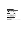

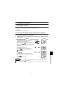

17
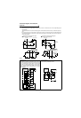
Connection diagram, PLG cable, PU
connector
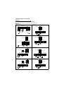
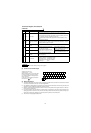
4) Sink logic type and source logic type
• The sink logic type is a logic where a signal turns on when a current flows out of the corresponding signal
input terminal.
Terminal SD is common to the contact input signals. Terminal SE is common to the open collector output sig-
nals.
• The source logic type is a logic where a signal turns on when a current flows into the corresponding signal
input terminal.Terminal PC is common to the contact input signals. Terminal SE is common to the open col-
lector output signals.
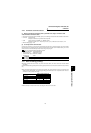
!
When using an external power supply for transistor output
• Sink logic type
Using terminal PC as a common terminal prevents a
malfunction caused by undesirable current. (Do not
connect terminal SD of the inverter with terminal 0V
of the external power supply. When using terminals
PC-SD as a 24VDC power supply, do not install a
power supply in parallel in the outside of the inverter.
Doing so may cause a malfunction due to undesir-
able current.)
• Source logic type
Use terminal SD as a common to prevent a malfunc-
tion caused by undesirable current.
RUN
SE
1
9
R
R
24VDC
24VDC
RUN
SE
1
9
R
R
Inverter
DC input (sink type)
<Example : AX40>
Inverter
DC input (source type)
<Example : AX80>
PC
STF
R
STR
R
Source logic
Current
Source
connector
SD
STF
R
STR
R
Sink logic
Current
Sink connector
Current flow concerning the RUN signal
when sink logic is selected
Current flow concerning the RUN signal
when source logic is selected
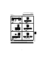
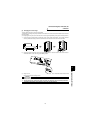
1
2
3
4
5
6
9
10
24VDC
SD
PC
RES
RL
RM
RH
STR
STF
24VDC
(SD)
Inverter
AY40 type
transistor
output module
9
1
2
10
PC
STF
STR
SD
24VDC
(SD)
24VDC
AY80 type
transistor
output module
Inverter