


1
1 OUTLINE
The "harmonic suppression guideline for household appliances and general-purpose products" was issued by the
Ministry of Economy, Trade and Industry (formerly Ministry of International Trade and Industry) in September, 1994.
This guideline applies to the 3.7K or less. By installing the power factor improving reactor (FR-BEL or FR-BAL), this
product conforms to the "harmonic suppression technique for transistorized inverters (input current 20A or less)" set
forth by the Japan Electrical Manufactures' Association.
For the 3.7K or more, refer to the Instruction Manual (detailed).
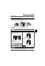
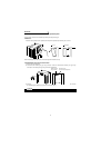
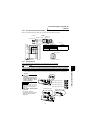
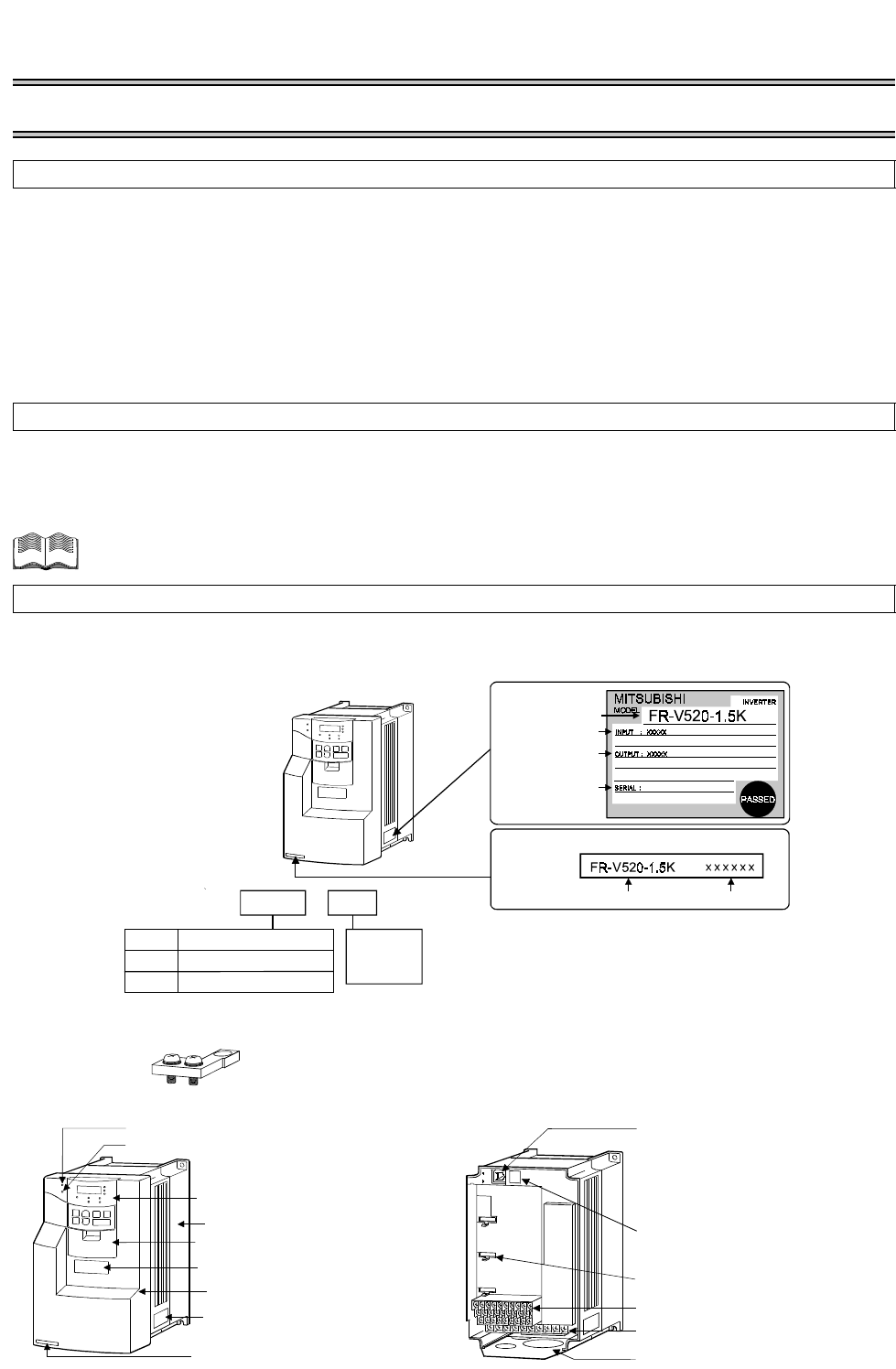
Unpack the inverter and check the capacity plate on the front cover and the rating plate on the inverter side face to
ensure that the product agrees with your order, an accessory L shaped jumper (Refer to page 15 for connection
method.)is included, and the inverter is intact.
<Abbreviations>
• DU: Operation panel (FR-DU04
-1
)
• PU: Operation panel (FR-DU04
-1
) and parameter unit (FR-PU04V)
• Inverter: Mitsubishi vector inverter FR-V500 series
• FR-V500: Mitsubishi vector inverter FR-V500 series
• Pr.: Parameter number
• PU operation: Operation using the PU (FR-DU04
-1
/FR-PU04V)
• External operation: Operation using the control circuit signals
• Combined operation: Operation using both the PU (FR-DU04
-1
/FR-PU04V) and external operation
• Dedicated motor: SF-V5R
• Standard motor (with PLG): SF-JR
• Constant-torque motor (with PLG): SF-HRCA
Harmonic Suppression Guideline
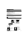
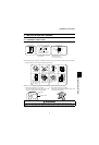
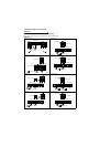
Product check and name of parts
(1) Front view
(2) Without front cover
*The 5.5K or less inverter is equipped with a built-in brake resistor and the 15K or less inverter is equipped
with a built-in brake transistor.
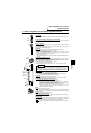
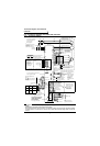
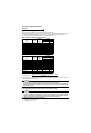
Plates
Inverter type Serial number
Capacity plate
Serial number
Rating plate
Inverter type
Input rating
Output rating
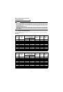
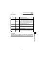
nverter type
FR
-
V520
-K
Inverter
capacity
(kW)
1.5
.
o. 5 terminal dedicated Lshaped jumper × 1 (supplied)
Symbol
V520
Three-phase 200V class
Voltage class
V540
Three-phase 400V class
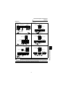
ALARM lamp
Wiring port cover for option
Front cover
POWER lamp
Accessory cover
Rating plate
Brake resistor* (Fitted to the back)
Operation panel (FR-DU04
-1
)
Capacity plate
.
Control circuit terminal block
Main circuit terminal block
PU Connector
(Provided with modular jack
type relay connector)
(For use with RS-485 cable
communication)
Modular jack type relay
connector compartment
Inboard option mounting positions
Wiring cover