


75
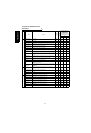
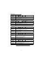
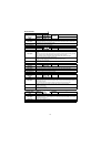
Errors (Alarms)
Operation Panel
Indication
E. 6
FR-PU04V
Fault 6
E. 7 Fault 7
Name
CPU error
Description
If the arithmetic operation of the peripheral circuit of the built-in CPU does not end within the
predetermined period or if an error exists in the receive data of the built-in CPU, the inverter self-
determines it as an alarm and stops the output.
Check point
—
Corrective action
Please contact your sales representative.
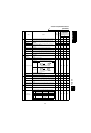
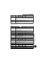
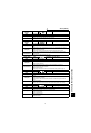
Operation Panel
Indication
E.P24 FR-PU04V E.P24
Name
24VDC power output short circuit
Description
When the 24VDC power output from the PC terminal is shorted, this function shuts off the power
output.
At this time, all external contact inputs switch off. The inverter cannot be reset by entering the RES
signal. To reset it, use the operation panel or switch power off, then on again.
When the 24VDC power for encoder is shorted, this function shuts off the power output.
Check point
• Check for a short circuit in the PC terminal output.
• Check for wrong wiring.
• Check for a loose connector. Check that the cables are short-circuited.
Corrective action
• Remedy the short circuit portion.
• Connect the cables securely. Change the cables.
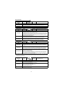
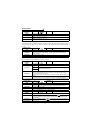
Operation Panel
Indication
E.P12 FR-PU04V E.P12
Name
12VDC power output short circuit
Description
When the 12VDC power for encoder is shorted, this function shuts off the power output.
Check point
• Check for wrong wiring.
• Check for a loose connector. Check for an open cable.
Corrective action
Connect the cables securely. Change the cables.
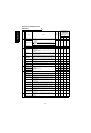
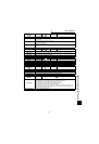
Operation Panel
Indication
E.CTE FR-PU04V —
Name
Operation panel power supply short circuit
Description
When the operation panel power supply (P5S of the PU connector) is shorted, this function shuts
off the power output. At this time, the operation panel (parameter unit) cannot be used and RS-485
communication from the PU connector cannot be made. To reset, enter the RES signal or switch
power off, then on again.
When the 5VDC power for encoder is shorted, this function shuts off the power output.
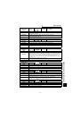
Check point
• Check for a short circuit in the PU connector cable. Check for a loose connector.
• Check that cables are short-circuited.
• Check for wrong wiring.
Corrective action
• Check the PU and cable.
• Connect the cable securely. Change the cable.
Operation Panel
Indication
E.MB1 to 7 FR-PU04V —
Name
Brake sequence error
Description
• The inverter output is stopped when a sequence error occurs during use of the brake sequence
function (Pr. 278 to Pr. 285).
• If (detection frequency) - (output frequency) > Pr. 285 under vector control, E.MB1 occurs and the
inverter output is stopped.
Check point
Find the cause of alarm occurrence.
Corrective action
Check the set parameters and perform wiring properly.
to