


8
INSTALLATION AND WIRING
2
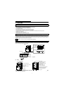
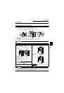
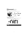
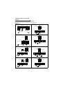
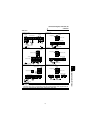
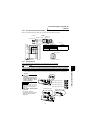
Connection diagram, PLG cable, PU
connector
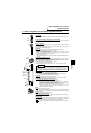
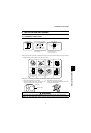
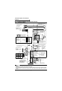
2.2.2 Main circuit
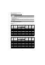
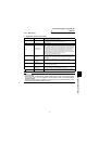
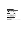
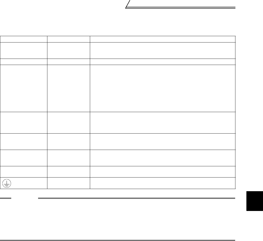
(1) Specification of main circuit terminal
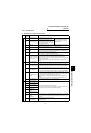
Terminal Symbol Terminal Name Description
R, S, T AC power input
Connect to the commercial power supply.
Keep these terminals open when using the high power factor converter (FR-
HC) or power regeneration common converter (FR-CV).
U, V, W Inverter output Connect a motor.
R1, S1
Power supply for
control circuit
Connected to the AC power supply terminals R and S. To retain the alarm
display and alarm output or when using the high power factor converter (FR-
HC) or power regeneration common converter (FR-CV), remove the jumpers
from terminals R-R1 and S-S1 and apply external power to these terminals.
Do not turn off the power supply for control circuit (R1, S1) with the main
circuit power (R, S, T) on. Doing so may damage the inverter. The circuit
should be configured so that the main circuit power (R, S, T) is also turned off
when the power supply for control circuit (R1, S1) is off.
15K or less : 60VA, 18.5K to 55K : 80VA
P, PR
Brake resistor
connection
Disconnect the jumper from terminals PR-PX (5.5K or less) and connect the
optional brake resistor (FR-ABR) across terminals P-PR.
For the 15K or less, connecting the resistor further provides regenerative
braking power.
P, N
Brake unit
connection
Connect the optional FR-BU brake unit, BU type brake unit, power
regeneration common converter (FR-CV) or high power factor converter (FR-
HC).
P, P1
Power factor
improving DC
reactor connection
Disconnect the jumper from terminals P-P1 and connect the optional power
factor improving reactor (FR-BEL).
PR, PX
Built-in brake circuit
connection
When the jumper is connected across terminals PX-PR (factory setting), the
built-in brake circuit is valid. (Provided for the 5.5K or less.)
Earth (Ground) For earthing (grounding) the inverter chassis. Must be earthed (grounded).
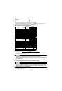
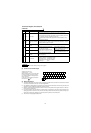
CAUTION
• The inverter will be damaged if power is applied to the inverter output terminals (U, V, W). Never per-
form such wiring.
• When connecting the dedicated brake resistor (FR-ABR), remove jumpers across terminals PR-PX
(5.5K or less). Set "1" in Pr. 30 "regenerative function selection". Refer to the Instruction Manual
(detailed) for details.
• When connecting the brake unit (FR-BU, BU), remove jumpers across terminals PR-PX (5.5K or less).
Refer to the Instruction Manual (detailed) for details.