


73
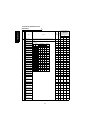
Errors (Alarms)
*5:The FR-A5NR (relay output/co
(Check the stall prevention operation level (Pr. 22) setting if V/F control is exer-
cised.)
mputer link) allows one more communication option to be fitted. In this case, only relay output is usable
and computer link is unusable.
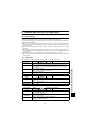
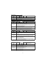
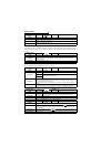
Operation Panel
Indication
E.OHT FR-PU04V OH Fault
Name
External thermal relay operation
Description
If the external thermal relay provided for motor overheat protection, or the internally mounted
temperature relay in the motor, etc. switches on (contacts open), the inverter output is stopped. If
the relay contacts are reset automatically, the inverter will not restart unless it is reset.
Check point
• Check for motor overheating.
Corrective action
Reduce the load and operating duty.
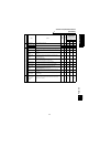
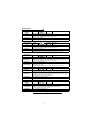
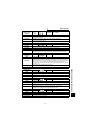
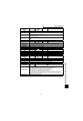
Operation Panel
Indication
E.OLT FR-PU04V
Stll Prev STP (OL shown during stall
prevention operation)
Name
Motor overload
Description
For V/F control, the stall prevention function is activated if the current flow in the motor exceeds
150% (factory setting) of the inverter rated current, an alarm stop is made if the status that the
output frequency is lowered at 0Hz persists for 3 seconds.
For speed/position control, if the torque restriction is activated under high load, the motor stalls to
the speed less than the low speed detection (Pr. 865) value, and an alarm stop is made if the status
that the output torque is more than the OLT level setting (Pr. 874) value persists for 3 seconds.
This function is not activated for torque control.
Check point
• Check the motor for use under overload.
• Check that the low speed detection (Pr. 865) and OLT level setting (Pr. 874) values are correct.
(Check the stall prevention operation level (Pr. 22) setting if V/F control is exercised.)
Corrective action
• Reduce the load weight.
• Change the low speed detection (Pr. 865) and OLT level setting (Pr. 874) values.
(Check the stall prevention operation level (Pr. 22) setting if V/F control is exercised.)
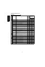
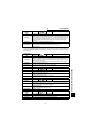
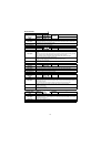
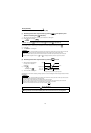
Operation Panel
Indication
E.OPT FR-PU04V Option Fault
Name Option alarm
Description
Stops the inverter output when two or more communication options are mounted. (*5)
When the high power factor converter (FR-HC) or power regeneration common converter (FR-CV)
is connected, this alarm appears if an AC power supply is connected to the R, S, T terminals
accidentally.
Check point
• Check that the number of communication options mounted is one.
• When the high power factor converter (FR-HC) or power regeneration common converter (FR-
CV) is connected, check that an AC power supply is not connected to the R, S, T terminals.
• When the parameter set is for the option use, the option is not fitted nor connected securely.
Corrective action
• Mount only one communication option.
• Check the Pr. 30 setting and wiring.
• Check the Pr. 419 and Pr. 804 settings.
• When the high power factor converter (FR-HC) or power regeneration common converter (FR-
CV) is connected, connecting an AC power supply to the R, S, T terminals may damage the
inverter. Please contact your sales representative.
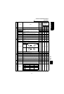
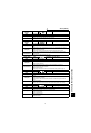
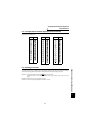
Operation Panel
Indication
E.OP1 to
OP3
FR-PU04V Option slot alarm 1 to 3
Name
Option slot alarm (1 to 3 indicate the option slot numbers.)
Description
Stops the inverter output if a functional alarm (e.g. communication line error of the communication
option or contact fault of the plug-in option other than the communication option) occurs in the plug-
in option fitted to the corresponding slot.
Check point
• Check for a wrong option function setting and operation.
• Check that the plug-in option is plugged into the connector securely.
• Check for an open communication cable.
• Check that the termination resistor is fitted properly.
• Check that the option card is normal.
Corrective action
• Check the option function setting, etc.
• Connect the plug-in option securely.
to