


9
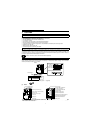
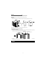
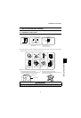
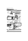
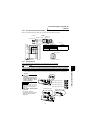
Connection diagram, PLG cable, PU
connector
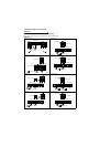
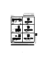
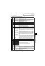
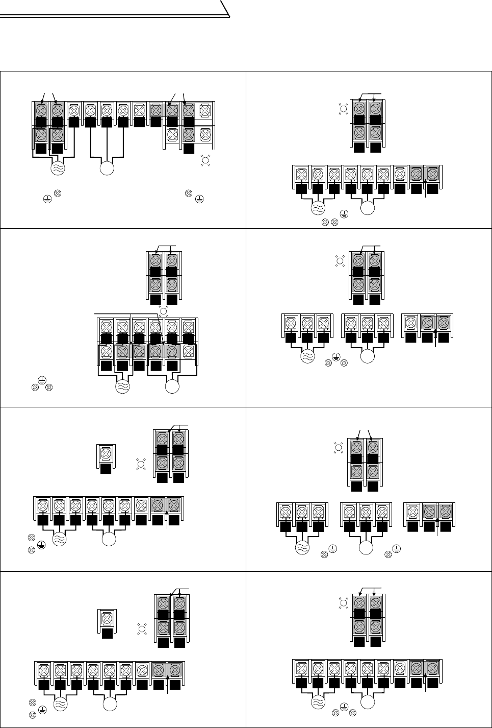
(2) Terminal arrangement of the main circuit terminal
In the main circuit of the inverter, the terminals are arranged as shown below:
200V class
FR-V520-1.5K, 2.2K FR-V520-18.5K
FR-V520-3.7K, 5.5K, 7.5K
7.5K is not provided with the PX terminal and PX-PR jumper.
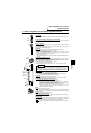
FR-V520-22K
FR-V520-11K FR-V520-30K, 37K
FR-V520-15K FR-V520-45K, 55K
P1
PX
PR
IM
UVW
S1R1
Jumpers
Screw size (M4)
Power supply
Motor
Screw size (M4)
Charge lamp
Jumpers
RTS
N
P
R1 S1
IM
P1
U V W
Charge lamp
Jumpers
Screw size (M4)
Screw size (M8)
Screw size (M6)
Jumper
R
NR
S
ST P
IM
UVW
P1 PR PX
R1 S1
Jumper
Screw size (M4)
Jumpers
Charge lamp
Screw size (M5)
Screw size (M5)
R
ST
RS
N
P
IM
P1U
V
W
R1 S1
Charge lamp
Jumpers
Screw size (M4)
Screw size (M8)
Jumper
Screw size (M6)
R
S
T
R
S
N
P
R1 S1
IM
P1
U V W
PR
Jumpers
Screw size (M5)
Jumper
Screw size (M6)
Charge
lamp
Screw size (M6)
Screw size (M4)
RS
T
N
P
RS
IM
P1
U
V W
R1 S1
Charge lamp
Jumpers
Screw size (M4)
Screw size (M10)
Jumper
Screw size (M8)
N
R
RS
ST
P
R1 S1
IM
P1
U V W
PR
Jumpers
Screw size (M4)
Jumper
Screw size (M8)
Charge
lamp
Screw size (M5)
Screw size (M6)
RS
T
RS
N
P
R1 S1
IM
P1
U V W
Charge lamp
Jumpers
Screw size (M4)
Screw size (M12)
Screw size (M8)
Jumper
R
NR
S
ST P