


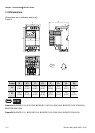
Chapter 2 Installation and Wiring| BLD-E1 Series
2-4 Revision May 2009, 00DE, V0.50
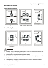
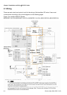
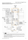
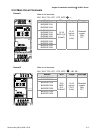
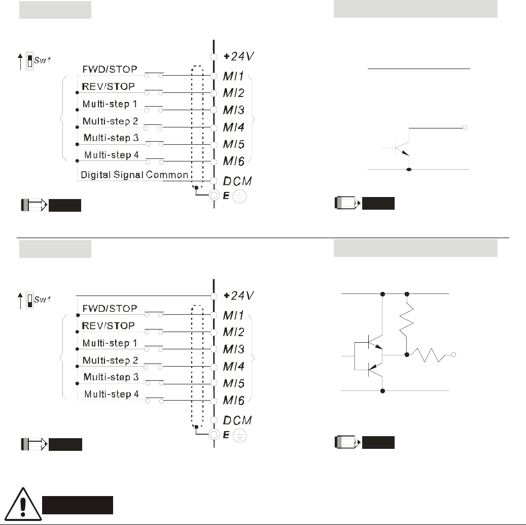
Figure 3 Wiring for NPN mode and PNP mode
NOTE
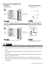
Factory
setting
NPN
PNP
Multi-function
input terminals
Don't apply mains voltage into above terminals.
NPN Mode
Factory setting is NPN
O/P
0V
VCC
NOTE
Open collector output
Applicable Output Signal
It needs to connect O/P to multi-function
input terminals for normal operation.
NOTE
Factory
setting
NPN
PNP
Multi-function
input terminals
Don't apply mains voltage into above terminals.
PNP Mode
Factory setting is PNP
NOTE
Complementary output
Applicable Output Signal
It needs to connect O/P to multi-function
input terminals for normal operation.
VCC
O/P
0V
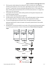
CAUTION!
1. The wiring of main circuit and control circuit should be separated to prevent erroneous actions.
2. Please use shield wire for the control wiring and not to expose the peeled-off net in front of the
terminal.
3. Please use the shield wire or tube for the power wiring and ground the two ends of the shield
wire or tube.
4. Damaged insulation of wiring may cause personal injury or damage to circuits/equipment if it
comes in contact with high voltage.
5. The brushless DC motor drive, motor and wiring may cause interference. To prevent the
equipment damage, please take care of the erroneous actions of the surrounding sensors and
the equipment.