


Chapter 4 Parameters| BLD-E1 Series
Revision May 2009, 00DE, V0.50 4-3
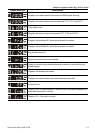
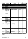
Paramete
r
Explanation Settings
Factory
Setting
VF VFPG FOCPM
5:defined by user (Pr.00-04)
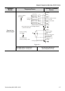
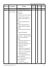
00.04 Content of Multi-
function Display
0:Display the output current from
drive to motor
1:Reserved
2:Display actual output frequency
3:Display DC-Bus voltage (U)
4:Display output voltage of U, V,
W (E)
5:Display output power factor
angle (n.)
6:Display output power (kW)
7:Display actual motor speed in
rpm (HU)
8:Display estimate output torque
(%)
9:Display PG feedback
10:Display the electrical angle of
drive output 11:Display the signal
value % of VR analog input
terminal
12:Display the signal value % of
ACI analog input terminal
13:Display the signal value % of
AVI analog input terminal
14:Reserved
15:Display IGBT temperature ℃
16:Digital input status ON/OFF
17:Digital output status ON/OFF
18:Multi-step speed (S)
19:The corresponding CPU pin
status of digital input
20:The corresponding CPU pin
status of digital output
21~23:Reserved
24:Output AC voltage when
0 ○ ○ ○