


Chapter 2 Installation and Wiring| BLD-E1 Series
2-8 Revision May 2009, 00DE, V0.50
When using a general GFCI (Ground Fault Circuit Interrupter), select a current sensor
with sensitivity of 200mA or above, and not less than 0.1-second operation time to avoid
nuisance tripping. For the specific GFCI of the brushless DC motor drive, please select a
current sensor with sensitivity of 30mA or above.
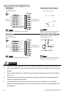
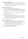
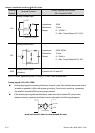
Output terminals for main circuit (U, V, W)
The factory setting of the operation direction is forward running.
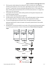
When it needs to install the filter at the output side of terminals U/T1, V/T2, W/T3 on the
brushless DC motor drive. Please use inductance filter. Do not use advanced capacitors
or L-C (Inductance-Capacitance) or R-C (Resistance-Capacitance), unless approved by
Delta.
DO NOT connect advanced capacitors or surge absorbers at the output terminals of
brushless DC motor drives.
Use well-insulated motor, suitable for drive operation.
When using a general GFCI (Ground Fault Circuit Interrupter), select a current sensor
with sensitivity of 200mA or above, and not less than 0.1-second operation time to avoid
nuisance tripping. For the specific GFCI of the brushless DC motor drive, please select a
current sensor with sensitivity of 30mA or above.
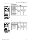
Terminals [+, -] for connecting brake resistor
Connect a brake resistor or brake unit in applications with frequent decelerations, short
deceleration time, insufficient brake torque or requiring increased brake torque.
When using external brake unit, please connect it to the terminals [+, -]. Please do NOT
connect brake resistors to terminals [+, -] directly, as it may cause damage.
All BLD-E1 series don’t have a built-in brake chopper. Please connect an external
optional brake unit (BUE-series) and brake resistor.
When not used, please leave the terminals [+, -] open.