


Chapter 4 ParametersAT |Troubleshooting}| BLD-E1 Series
4-36
Revision May 2009, 00DE, V0.50
0: OFF, 1: ON
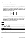
MI3: Pr.02-01 is set to 1 (multi-step speed command 1)
MI6: Pr.02-04 is set to 8 (the 1st, 2nd acceleration/deceleration time selection)
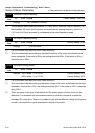
If REV, MI2, MI3 and MI6 are ON, the value is 0000 0000 0010 0110B in binary and 0026H in
HEX. At the meanwhile, if Pr.00-04 is set to “16” or “19”, it will display “0026” with LED U is ON
on the keypad KPVL-CC01. The setting 16 is the status of digital input and the setting 19 is the
corresponding CPU pin status of digital input. User can set to 16 to monitor digital input status
and then set to 19 to check if the wire is normal.
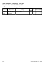
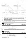
Terminal MO2 MO1
Status
0 1
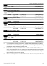
RA: Pr.02-13 is set to 9 (Drive ready).
After applying the power to the brushless DC motor drive, if there is no other abnormal status,
the contact will be ON. At the meanwhile, if Pr.00-04 is set to 17 or 20, it will display 0001 with
LED U is ON on the keypad. The setting 17 is the status of digital output and the setting 20 is
the corresponding CPU pin status of digital output. User can set 17 to monitor the digital
output status and then set to 20 to check if the wire if normal.
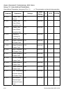
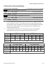
00-05
Reserved
00-06
Software Version
Control
mode
VF VFPG FOCPM
Factory setting: #.##
Settings Read Only
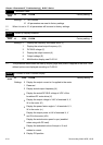
00-07
Selection of motor stop method
Control
mode
VF VFPG FOCPM
Factory setting: 0
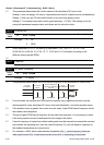
Settings 0: ramp to stop
1: coast to stop
As the drive receives “stop” command, the stop method will be according to this parameter
setting.