


Chapter 4 Parameters| BLD-E1 Series
Revision May 2009, 00DE, V0.50 4-35
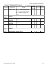
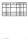
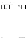
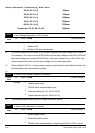
00-04
Content of Multi-Function Display
10 Display the electrical angle of drive output
11
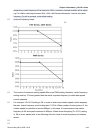
Display the signal of VR analog input terminal in %.
Range 0~10V corresponds to 0~100%.
12
Display the signal of ACI analog input terminal in %.
Range 4~20mA/0~10V corresponds to 0~100%.
13
Display the signal of AVI analog input terminal in %.
Range -10V~10V corresponds to 0~100%.
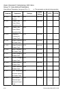
14 Reserved
15 Display the temperature of IGBT in °C.
16 Display digital input status ON/OFF
17 Display digital output status ON/OFF
18 Display multi-step speed
19 The corresponding CPU pin status of digital input
20 The corresponding CPU pin status of digital output
21
|
23
Reserved
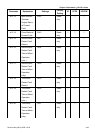
24 Output AC voltage when malfunction
25 Output DC voltage when malfunction
26 Motor frequency when malfunction
27 Output current when malfunction
28 Output frequency when malfunction
29 Frequency command when malfunction
30 Output power when malfunction
31 Output torque when malfunction
32 Input terminal status when malfunction
33 Output terminal status when malfunction
34 Drive status when malfunction
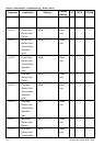
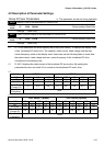
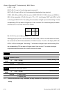
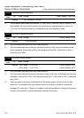
It is used to display the content when LED U is ON. It is helpful for getting the brushless DC
motor drive’s status by this parameter.
Terminal MI8 MI7 MI6 MI5 MI4 MI3 MI2 MI1 REV FWD
Status 0 0 1 0 0 0 0 1 1 0