


Chapter 2 Installation and Wiring| BLD-E1 Series
Revision May 2009, 00DE, V0.50 2-11
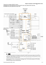
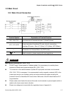
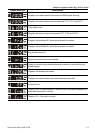
Terminal
Symbol
Terminal Function
Factory Settings (NPN mode)
ON: Connect to DCM
+24V DC Voltage Source +24VDC, 20mA
DCM Digital Signal Common Common for digital inputs
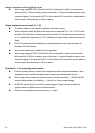
HU/U Reserved
HV/V Reserved
HW/W Reserved
A PG feedback signal contact 1
Sending PG signals to the drive, e.g. activation,
operation, speed control etc.
B PG feedback signal contact 2
Sending PG signals to the drive, e.g. activation,
operation, speed control etc.
Z/PWM
PG feedback signal contact
PWM
Sending PMW signals to the drive to activate at
the origin position.
SPO Reserved
+5V Encoder Power Supply
GND Feedback Signal Common
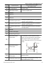
MO1
Multi-function Output 1
(Photocoupler)
MO2
Multi-function Output 2
(Photocoupler)
The brushless DC motor monitors all kinds of
signal, such as during operation, speed attained
and overload indication, by the open collector
output. Please refer to Pr.02-13, Pr.02-14 for more
details.
MCM
Multi-function output common
(Photocoupler)
Max 48Vdc 50mA
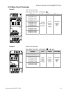
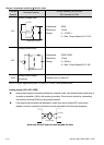
+10V Potentiometer power supply
Power supply for analog frequency setting +10VDC
3mA (variable resistor 3~5kΩ)
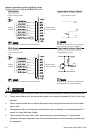
+5V
MCM
Max:
48VDC/50mA
internal circuit