


Chapter 2 Installation and Wiring| BLD-E1 Series
2-6 Revision May 2009, 00DE, V0.50
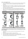
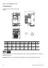
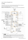
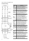
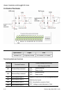
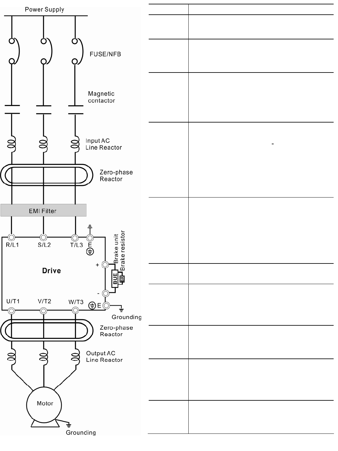
2.2 External Wiring
Items Explanations
Power
supply
Please follow the specific power supply
requirements shown in Appendix A.
Fuse/NFB
(Optional)
There may be an inrush current during
power up. Please check the chart of
Appendix B and select the correct fuse with
rated current. Use of an NFB is optional.
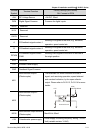
Magnetic
contactor
(Optional)
Do NOT run/stop brushless DC motor drives
by turning the magnetic contactor ON/OFF,
as it will reduce the usage life of drive. If you
still need to run/stop drives by turning the
magnetic contactor ON/OFF, it is
recommended to do so only ONCE per hour.
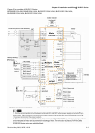
Input AC
Line
Reactor
(Optional)
Used to improve the input power factor, to
reduce harmonics and provide protection
from AC line disturbances.
(surges,
switching spikes and short interruptions). AC
line reactor should be installed when the
power supply capacity is 500kVA or more or
advanced capacity is activated .The wiring
distance should be
≤
10m. Refer to
appendix B for details.
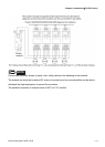
Zero-phase
Reactor
(Ferrite
Core
Common
Choke)
(Optional)
Zero phase reactors are used to reduce
radio noise especially when audio equipment
is installed near the brushless DC motor
drive. Effective for noise reduction on both
the input and output sides. Attenuation
quality is good for a wide range from AM
band to 10MHz. Appendix B specifies the
zero phase reactor. (RF220X00A)
EMI filter
To reduce electromagnetic interference. It is
built in 230V 1-phase and 460V models.
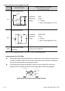
Driver
The surrounding temperature should be
within the specification (refer to chapter 1) to
prevent from reducing the drive’s usage life.
Please wire according to chapter 2 wiring,
wrong wire may cause damage.
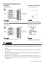
Brake
resistor
and Brake
unit
Used to reduce the deceleration time of the
motor. Please refer to the chart in Appendix
B for specific Brake resistors.
Output AC
Line
Reactor
Motor surge voltage amplitude depends on
motor cable length. For applications with
long motor cable (>20m), it is necessary to
install a reactor at the drive output side.
Please refer to the chart in appendix B.
Grounding
To prevent electric shock due to leakage
current of the drive, the drive and motor
should be grounded. Please refer to
specification of main circuit terminal.