


Chapter 2 Installation and Wiring| BLD-E1 Series
2-12 Revision May 2009, 00DE, V0.50
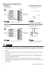
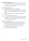
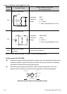
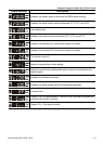
Terminal
Symbol
Terminal Function
Factory Settings (NPN mode)
ON: Connect to DCM
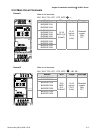
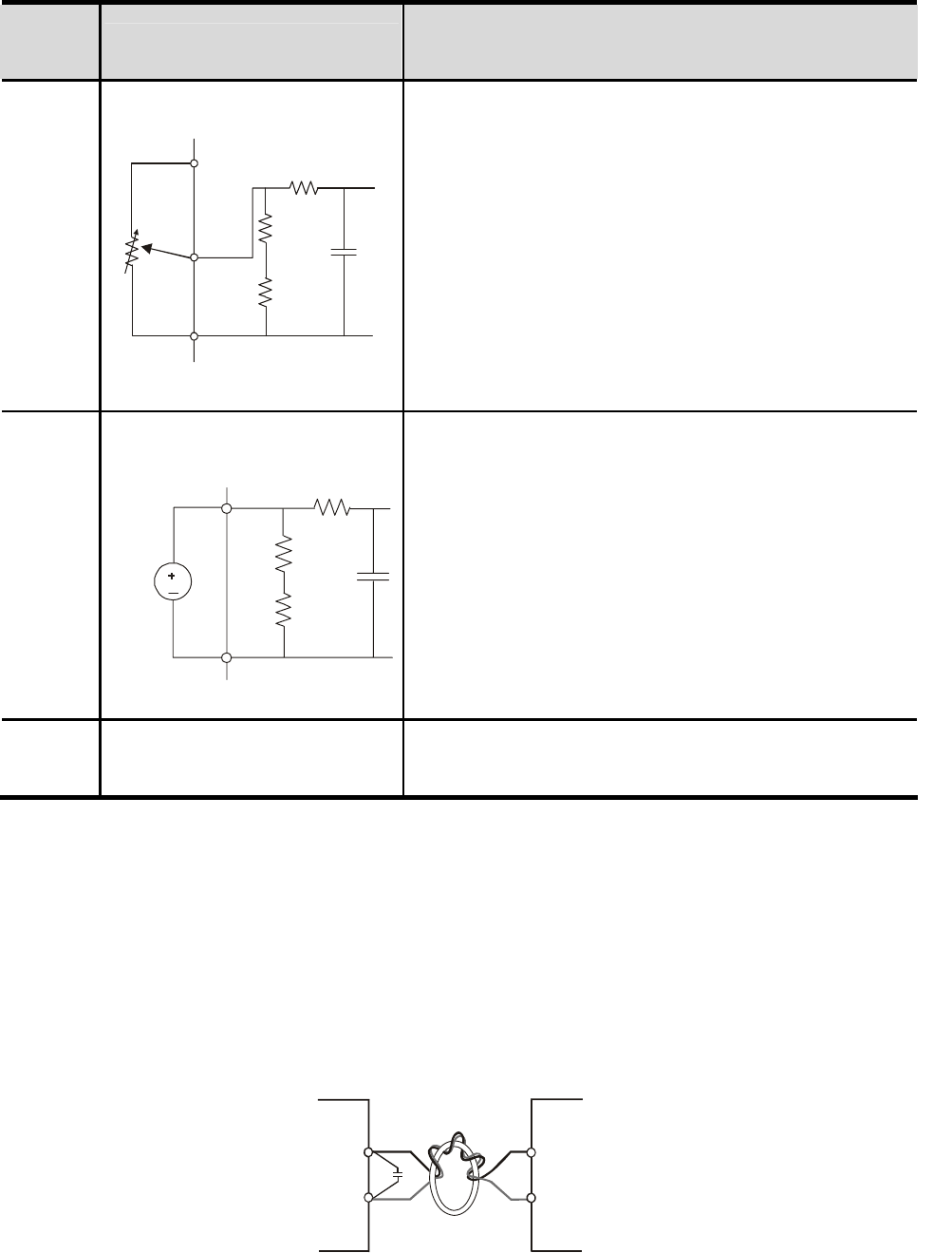
AVI
Analog voltage Input
Impedance: 20kΩ
Resolution: 10 bits
Range: 0 ~ 10VDC =
0 ~ Max. Output Speed (Pr.01-00)
ACI
Analog current Input
Impedance: 250Ω/100kΩ
Resolution: 10 bits
Range: 4 ~ 20mA =
0 ~ Max. Output Speed(Pr.01-00)
ACM
Analog control signal
(common)
Common for AVI and ACI
NOTE: Control signal wiring size: 18 AWG (0.75 mm
2
) with shielded wire
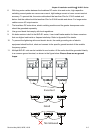
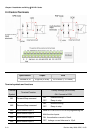
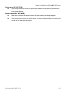
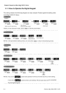
Analog inputs (AVI, ACI, ACM)
Analog input signals are easily affected by external noise. Use shielded wiring and keep it
as short as possible (<20m) with proper grounding. If the noise is inductive, connecting
the shield to terminal ACM can bring improvement.
If the analog input signals are affected by noise from the brushless DC motor drive,
please connect a capacitor and ferrite core as indicated in the following diagrams:
C
AVI/ACI
ACM
ferrite core
wind each wires 3 times or more around the core
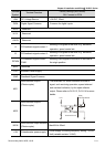
A
CM
A
VI
+10V
internal circuit
A
CM
A
CI
DC
internal circuit