


Chapter 4 ParametersAT |Troubleshooting}| BLD-E1 Series
4-40
Revision May 2009, 00DE, V0.50
2K (Pr. 00-12 = 2) 900rpm
3K (Pr. 00-12 = 3) 1350rpm
4K (Pr. 00-12 = 4) 1800rpm
5K (Pr. 00-12 = 5) 2250rpm
6K (Pr. 00-12 = 6) 2700rpm
Greater than 7K (Pr. 00-12 >7K) 3000rpm
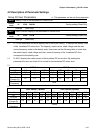
00-13
Auto Voltage Regulation (AVR) Function
Control
mode
VF VFPG FOCPM
Factory setting: 0
Settings 0 Enable AVR
1 Disable AVR
2 Disable AVR when deceleration
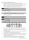
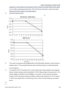
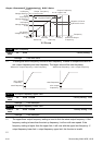
It is used to select the AVR mode. AVR is used to regulate the output voltage to the motor.
For example, if V/f curve is set to AC200V/50Hz and the input voltage is from 200 to 264VAC,
the output voltage won’t excess AC200V/50Hz. If the input voltage is from 180 to 200V, the
output voltage to the motor and the input voltage will be in direct proportion.
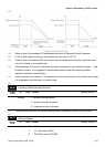
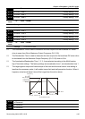
When setting Pr.00-13 to 1 during ramp to stop and used with auto accel./decel. function, the
the deceleration will be smoother and faster.
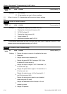
00-14
Source of the Master Frequency Command
Control
mode
VF VFPG FOCPM
Factory setting: 2
Settings 0
Digital keypad input
1
RS-485 serial communication input
2
External analog input (Pr. 03-00~03-02)
3
Digital terminals input (Pr.04-00~04-15)
This parameter determines the drive’s master frequency source.
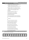
00-15
Source of the Operation Command
Control
mode
VF VFPG FOCPM
Factory setting: 0
Settings 0
Digital keypad control
1
External terminal control
2
RS-485 serial communication or digital keypad (KPVL-CC01) control