


CPF180i and CPF300i Page 21
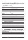
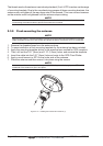
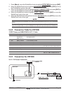
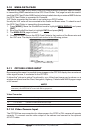
Ø8 mm [0.31"]
Ø3.2mm [0.13”]
GPS OVERALL SHAPE
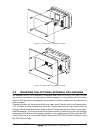
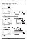
Figure 2.3.0a - Installing the External GPS Antenna (II)
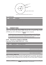
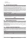
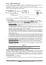
Smart GPS Cable
Pin Wire Color Description
1 Red Battery Positive
2 Green Smart GPS NMEA Output
3 Brown Smart GPS NMEA Input
4NC
5NC
6 Black/Yellow Battery Ground
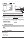
2.4 CONNECTIONS
The CPF180i and CPF300i have connector that allow them to be connected to a power
supply, option WAAS GPS antenna, NMEA Devices such as Optional Video Camera
(CPF300i only) VHF’s, AIS Receiver, Digital Instruments, Autopilots.
NOTE
The GPS Chart Plotter can send many sentences to external NMEA devices. The NMEA Output
wires are Yellow and White (CPF180i and CPF300i) and White (CPF300i). If you have connected
devices as shown in the below table and need to feed NMEA to other devices (Autopilot, RADAR…)
you can parallel wires from the Yellow, Brown or White wires to other devices.
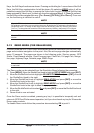
2.4.0 Connection Table For CPF180i
Power Data Cable and NMEA PWR & ACC 1 Cable
Pin Wire Color Description Connection Example Additional Comments
1 Black Battery Ground Connect to Battery Ground
2 Red Battery Positive Connect to Battery Positive
3 Green NMEA Common Common (ground) for NMEA devices
4 Blue Port1 Input Connect to Output of NMEA device Default is NMEA0183
5 Brown Port1 Output Connect to Input of NMEA device Default is NMEA0183 with GGA, GLL, RMC,
DBT, DPT, MTW, VHW and XTE sentences
6 Gray NC
7 White NC
8 Yellow Port 3 Output
Connect to Input of NMEA device Default is NMEA0183 with APA, APB, BOD,
GGA, GLL, RMC and XTE sentences*
*NOTE: AUTOPILOT CONNECTION
Care must be taken when connecting the GPS Chart Plotter to an autopilot. Normally Port
3 (Yellow wire) will be used to connect to an Autopilot input, however older autopilots may
not be able to read the sentences due to the talker ID that is being used (II Integrated