


Page 92 CPF180i and CPF300i
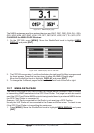
a. In Home mode the GPS Chart Plotter centers the location of the vessel in the center
of the display. To keep the vessel in the center of the display the GPS Chart Plotter
will occasionally redraw.
b. If the vessel changes course greater than 330T or more than 30T the chart will be
redrawn.
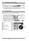
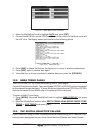
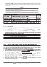
Static Navigation : Sets up a threshold for the speed. When the speed received from the positioning device
is under that threshold, the GPS Chart Plotter displays zero. The default setting is 0.9 Kts.
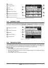
13.1.0 Loran TD
The Loran TD selection allows the GPS Chart Plotter to be set up so the user can enter in
LORAN TD’s directly into the GPS Chart Plotter. After the TD’s have been entered, and the
user changes to ddd mm.sss (Degrees Minutes and Seconds) the TD’s will be converted
to Lat / Lon coordinates.
To use the TD Coordinate System the user must setup the Chain and Pair information of
the TD’s. If you do not know this information, refer to paper charts that show the Chain and
Pair information.
ASF1/2 : Additional Secondary phase Factor (TD Coordinate System)
Correction to TD1/2 values which can be inserted by the user to take in account the
additional signal propagation delay aver a mixed land/seawater path compared to on all-
seawater path. Normally the user does not enter a ASF value. However for experienced
users this function allows entering of signal delay values to fine adjust the calculated
position. The user should enter delay values to fine adjust the position calculated.
Alter : Alternate Solution (TD Coordinate System)
Parameter selected by the user that is applied in the conversion of geographical coordinates
Lat/Lon to TD values. To be used if the position displayed is roughly not correct.
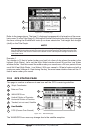
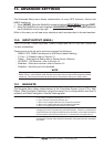
13.2 COMPASS
The GPS Chart Plotter computes compass direction from the constellation of GPS
Satellites. For the GPS Chart Plotter to compute direction the vessel must be moving
through the water. This menu allows the GPS Chart Plotter to customize the following
selections:
Bearings : Selects between True and Magnetic. When Magnetic bearings is enabled, the GPS Chart Plotter applies
the selected Magnetic Variation (Auto or Manual, see next paragraph) to compute True bearing.
Variation : Allows the user to select Auto or Manual. When Auto mode is selected the GPS Chart Plotter computes
the offset by the current GPS fixed location. Manual mode allows the user to enter in a magnetic variation
that is applied in the True conversion.
Calibration : This function allows a user to enter in the offset for areas that the vessel may cruise instead of entering
in a manual offset for one location. This offset is useful for cruising vessels or vessels that travel
internationally often.
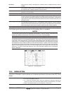
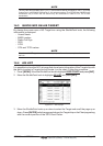
Figure 13.2 - Compass Table
13.3 ALARMS
This menu is used to select and setup audible and visual Alarms. Available alarms are
Arrival, XTE, Depth, Anchor and Grounding Alarm.
Arrival Alarm : Alerts when the vessel is approaching a single destination point or when arriving at a leg
in a Route. Available selections: 0.00 to 9.99NM.