


6. INSTALLATION AND WIRING
6-6
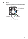
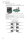
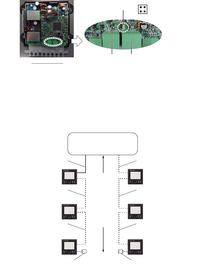
6.2.1 Wiring notices
Keep the following wiring notices in mind.
• To connect a single control unit, use pin no. 1 to 7 of the TB8 port.
• To use both lines of the TB8 port, short pin #3-#4 of the jumper block J104 (default
setting: #1-#2 short).
• To connect the control unit to processor unit, use the cable assy. (type: BD-
07AFFM-LR-150).
• To connect the control units in a daisy chain connection, use the optional cable as-
sy. (type: BD-07AF-07AF-LR-100).
• Attach the terminator (type: BD-07AFFM-LR7001) to the port not used on the last
control unit in the series. If the terminator is not attached, the control unit may not
work properly.
• The total length of cables in a series must be within 30 m.
TB13 TB8
12
34
J104
Processor unit
Cable assy.
䋨BD-07AFFM-LR-150䋩
Cable assy.
䋨BD-07AF-07AF-LR-100䋩
Cable assy.
䋨BD-07AF-07AF-LR-100䋩
Cable assy.
䋨BD-07AFFM-LR-150䋩
Cable assy.
䋨BD-07AF-07AF-LR-100䋩
Cable assy.
䋨BD-07AF-07AF-LR-100䋩
Terminator
䋨BD-07AFFM-LR7001䋩
Terminator
䋨BD-07AFFM-LR7001䋩
Total length of cables
Max 30 m
Processor unit
TB8
䋨#1 to #7 pin䋩
TB8
䋨#8 to #14 pin䋩