


6. INSTALLATION AND WIRING
6-8
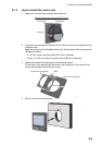
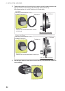
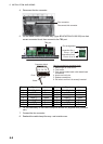
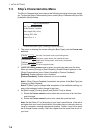
4. Disconnect the fan connector.
5. Put the cable cores of the cable assy. (type: BD-07AFFM-LR-100/150) into their
correct connector block, then connect to the TB8 port.
6. Fix the cable assy. to the cable clamp with a cable tie (supplied with processor
unit).
7. Connect the fan connector.
8. Reattach the cable clamp/fan assy. and outside cover.
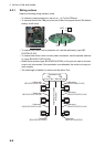
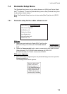
Pin no. Signal Color Pin no. Signal Color
1 POWER_SW1 White 8 POWER_SW2 White
2 GND Blue 9 GND Blue
3 CAN1_H Yellow 10 CAN2_H Yellow
4 CAN1_L Green 11 CAN2_L Green
5 12V_P Red 12 12V_P Red
6 GND Black 13 GND Black
7 SHIELD Drain 14 SHIELD Drain
Fan connector:
Disconnect this connector
㪍㩷㫄㫄
㪈㪉㪊㪋
㪌
㪌
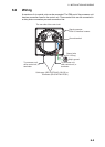
Cable entrance of the processor unit
TB8 port
Pin arrangement
Connection line 1
Pin no.: 1 to 7
㪍
㪍
㪎
㪎
TB8 port
Connection line 2
Pin no.: 8 to 14
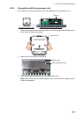
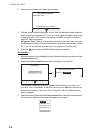
Connector block
Push
Cores
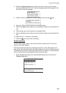
How to put wire into connector block
1. Make length of cores 6 mm.
2. Twist cores.
3. Push spring-loaded catch with slotted-head
screwdriver.
4. Insert core into hole.
5. Release screwdriver.
6. Pull wire to confirm it is securely inserted.