


BBV28581 05/2010 101
Migration ATV11 - ATV12
Terminals
Power
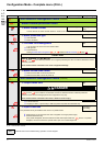
• Before wiring power terminals, connect the ground terminal of the grounding screws located below the output terminals to the
protective ground (see indicator B page 20
).
• The power connections are available without removing the power terminal cover. Nevertheless, if necessary, it is possible to remove
them using an adapted tool (IP20 protection requirement). Cover to be removed in case of using ring terminals (pressure stress is
14 N for size 1 and 20 N for sizes 2 and 3).
• Pay attention to the input ground terminal located on the right of the connector
(was on left on ATV11). The ground connection is
clearly indicated on the input power terminal cover and the screw colour is green.
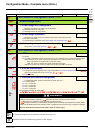
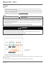
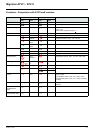
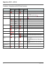
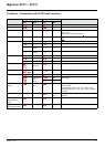
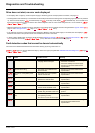
Control
Note: The control terminals are arranged and marked differently:
(1) On ATV11 DO is an analog output that can be configured as a logic output. On ATV12, depending on your configuration, DO can be
linked to LO1 or AO1.
The ATV11 integrates an internal supply voltage of 15V, ATV12 now integrates an internal supply of 24V.
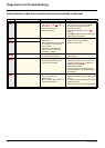
WARNING
IMPROPER CONTROL WIRING PRACTICES
• The ATV12 drive internal supply is 24 V rather than 15 V on ATV11. When replacing ATV11 drive with an ATV12, a voltage adaptor,
reference VW3A9317 must be connected to the 24 V supply if it is used to supply external automation systems. Using the 24 V to
supply the LI does not required any adaptor.
• When replacing ATV11 drive with an ATV12 drive, verify that all wiring connections to the ATV12 drive comply with all wiring
instructions in this manual.
Failure to follow these instructions can result in death, serious injury, or equipment damage.
DANGER
HAZARD OF ELECTRIC SHOCK, EXPLOSION, OR ARC FLASH
• The drive panel must be properly grounded before power is applied.
• Use the provided ground connecting point. The ground terminal (green screw) is at the opposite location it was on the ATV11.
Failure to follow these instructions will result in death or serious injury.
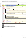
(1) if "DO" has been
used on ATV11
ATV11
LI1
LI3
LI2
LI4
+15V
AI1
+5V
DO
RA
RC
not used
0V
R1A
R1B
R1C
COM
AI1
5V
AO1
LO+
LO-
COM
LI1
LI2
LI3
LI4
+24V
ATV12
(1)