


BBV28581 05/2010 59
Configuration Mode - Complete menu (FULL)
Code
Name/Description Adjustment range Factory setting
drC-
Motor control menu (continued)
PFL
T
M Flux Profile
0 to 100% 20%
It defines the magnetizing current at zero frequency, as a % of the rated magnetizing current
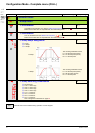
Adjustment of PUMP law.
Frequency
Visible only if Motor control type Ctt page 57
is set to PUMP
SFr
T
M Switching frequency
2 to 16 kHz 4 kHz
Switching frequency setting.
In the event of overheating, the drive automatically decreases the switching frequency.
It is restored to its original value when the temperature returns to normal.
CAUTION
RISK OF DAMAGE TO THE DRIVE
On ATV12ppppM2 ratings, if the filters are disconnected, the drive’s switching frequency must not exceed 4 kHz.
Failure to follow these instructions can result in equipment damage.
SFt
M Switching frequency type
HF1
HF1
HF2
The motor switching frequency will always be modified (reduced) when the internal temperature of the
drive is too high.
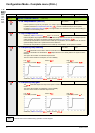
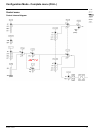
v HF1: Heating optimization.
Allows the system to adapt the switching frequency according to the motor frequency.
v HF2: Motor noise optimization (for high switching fequency).
Allows system to keep a constant chosen switching frequency (SFr) whatever the motor frequency (rFr).
In the event of overheating, the drive automatically decreases the switching frequency.
It is restored to its original value when the temperature returns to normal.
nrd
M Motor noise reduction
nO
nO
YES
Noise means audible noise. Depending on the environment it must be possible to adjust the motor noise.
Random frequency modulation avoids possible resonance noises that can occur at fixed frequency.
v No
v Yes
T
Parameter that can be modified during operation or when stopped.
I-O-
drC-
CtL-
FUN-
FLt-
COM-