


16 BBV28581 05/2010
Wiring
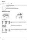
Recommendations
Keep the power cables separate from control circuits with low-level signals (detectors, PLCs, measuring apparatus, video, telephone).
Always cross control and power cables at 90° if possible.
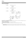
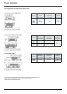
Power and circuit protection
Follow wire size recommendations according to local codes and standards.
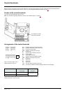
Before wiring power terminals, connect the ground terminal to the grounding screws located below the output terminals (see Access to the
motor terminals if you use ring terminals, page 21
.
The drive must be grounded in accordance with the applicable safety standards. ATV12
ppppM2 drives have an internal EMC filter, and as
such the leakage current is over 3.5 mA.
When upstream protection by means of a "residual current device" is required by the installation standards, a type A circuit breaker should
be used for single-phase drives and type B for 3-phase drives. Choose a suitable model incorporating:
• HF current filtering
• A time delay which prevents tripping caused by the load from stray capacitance on power-up. The time delay is not possible for 30 mA
devices. In this case, choose devices with immunity against accidental tripping, for example RCDs with SI type leakage current
protection.
If the installation includes several drives, provide one "residual current device" per drive.
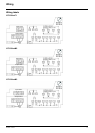
Control
For control and speed reference circuits, we recommend using shielded twisted cables with a pitch of between 25 and 50 mm (1 and 2 in.),
connecting the shield to ground as outlined on page 26
.
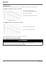
Length of motor cables
For motor cable lengths longer than 50 m (164 ft) for shielded cables and longer than 100 m (328 ft) for unshielded cables, please use motor
chokes.
For accessory part numbers, please refer to the catalog.
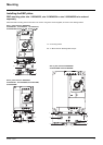
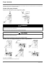
Equipment grounding
Ground the drive according to local and national code requirements. A minimum wire size of 10 mm² (6 AWG) may be required to meet
standards limiting leakage current.
.
DANGER
HAZARD OF ELECTRIC SHOCK, EXPLOSION, OR ARC FLASH
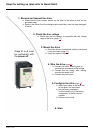
• The drive panel must be properly grounded before power is applied.
• Use the provided ground connecting point as shown in the figure below.
Failure to follow these instructions will result in death or serious injury.
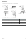
DANGER
ATV12H075F1, ATV12H075M2 AND ATV12H075M3 - GROUND CONTINUITY HAZARD
An anodized heatsink can create an insulation barrier to the mounting surface. Ensure that you follow the recommended grounding
connections.
Failure to follow these instructions will result in death or serious injury.
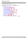
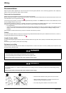
• Ensure that the resistance of the ground is one ohm or less.
• When grounding several drives, you must connect each one
directly, as shown in the figure to the left.
• Do not loop the ground cables or connect them in series.