


30 BBV28581 05/2010
Factory configuration
Drive factory settings
The Altivar 12 is factory-set for the most common operating conditions (motor rating according to drive rating):
• Display: drive ready (rdY) motor stopped or motor frequency reference while running
• Automatic adaptation of the deceleration ramp in the event of overvoltage on braking.
• No automatic restarting after a detected fault is cleared
• Logic inputs:
- LI1: forward (2-wire transitional control)
- LI2, LI3, LI4: no assignment
• Logic output: LO1: no assignment
• Analog input: AI1 (0 to + 5 V) speed reference
• Relay R1: the contact opens in the event of a detected fault (or drive off)
• Analog output AO1: no assignment
If the above values are compatible with the application, the drive can be used without changing the settings.
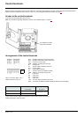
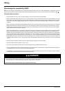
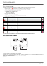
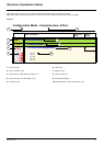
Drive factory wiring diagram
(1) R1 relay contacts, for remote indication of the drive status.
(2) Internal + 24 V
c. If an external source is used (+ 30 V c maximum), connect the 0 V of the source to the COM terminal, and do not
use the + 24 V
c terminal on the drive.
(3) Reference potentiometer SZ1RV1202 (2.2 k
Ω) or similar (10 kΩ maximum).
(4) Forward
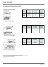
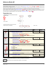
Code Description Value
page
bFr Standard motor frequency 50 Hz
45
UnS Rated motor voltage 230 V
57
ACC Acceleration 3 seconds
64
dEC Deceleration 3 seconds
64
LSP Low speed 0 Hz
45
89
HSP High speed 50 Hz
90
Ctt Motor control type Standard U/F law
57
UFr IR compensation (law U/F) 100%
58
Ith Motor thermal current equal to nominal motor current (value determined by drive rating)
94
SdC1 Automatic DC injection current 0.7 x nominal drive current, for 0.5 seconds.
67
SFr Switching frequency 4 kHz
59
U/T1
V/T2
W/T3
PA / +
COM
AI1
+5V
AO1
U1
W1
V1
M
3 a
LI1
LO+
LO-
COM
R1B
R1C
LI2
LI3
LI4
+24 V
PC / -
R1A
R/L1
S/L2
T/L3
(1) (3)
(2)
(4)
ac
b
ATV12ppppM3
3-phase
motor
Source